AFE1_AFE2-1:1
I-jet
19
The JTAG/SWD - MIPI-10 cable
I-jet also comes with a 6-inch cable with a 20-pin MIPI connector on one side (to
connect to I-jet) and a 10-pin MIPI connector on the other side for connection to Cortex
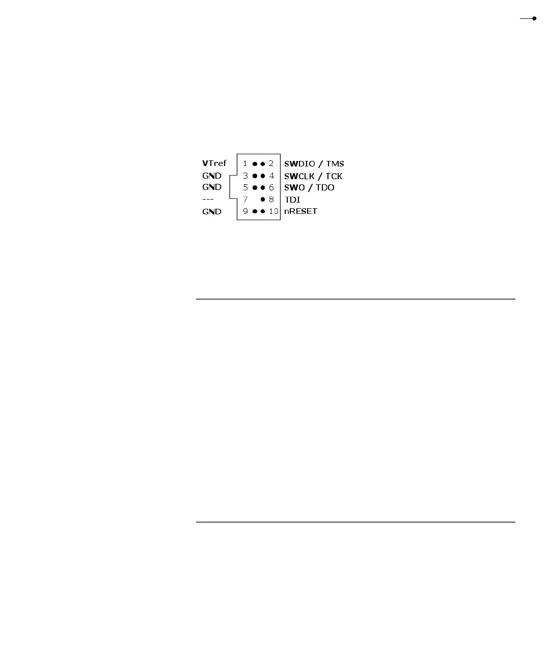
devices with 10-pin headers. Pin 7 on each end is keyed with a white plug:
The mating connector for a target board has the pitch size 0.05 in (1.27 mm). You can,
for example, use part number SHF-105-01-L-D.
These are the MIPI-10 pin definitions:
Pin Signal Type Description
1 VTref Input The target reference voltage. Used by I-jet to check
whether the target has power, to create the logic-level
reference for the input comparators, and to control the
output logic levels to the target. It is normally fed from
JTAG I/O voltage.
2 SWDIO/TMS I/O, output JTAG mode set input of target CPU. This pin should be
pulled up on the target. Typically connected to TMS of the
target CPU.
3 GND GND Connected to logic GND on I-jet.
4 SWCLK/TCK Output JTAG clock signal to target CPU. It is recommended that
this pin is pulled to a defined state of the target board.
Typically connected to TCK of the target CPU.
5 GND GND Connected to logic GND on I-jet.
6 SWO/TDO Input JTAG data output from target CPU. Typically connected to
TDO of the target CPU. When using SWD, this pin is used
as Serial Wire Output (SWO) trace port. (Optional, not
required for SWD communication.)
7-- KEY KEY or GND.
Table 4: MIPI-10 pin definitions