AFE1_AFE2-1:1
38
Introduction
IAR Debug Probes User Guide
I-jet®, I-jet Trace, and I-scope™
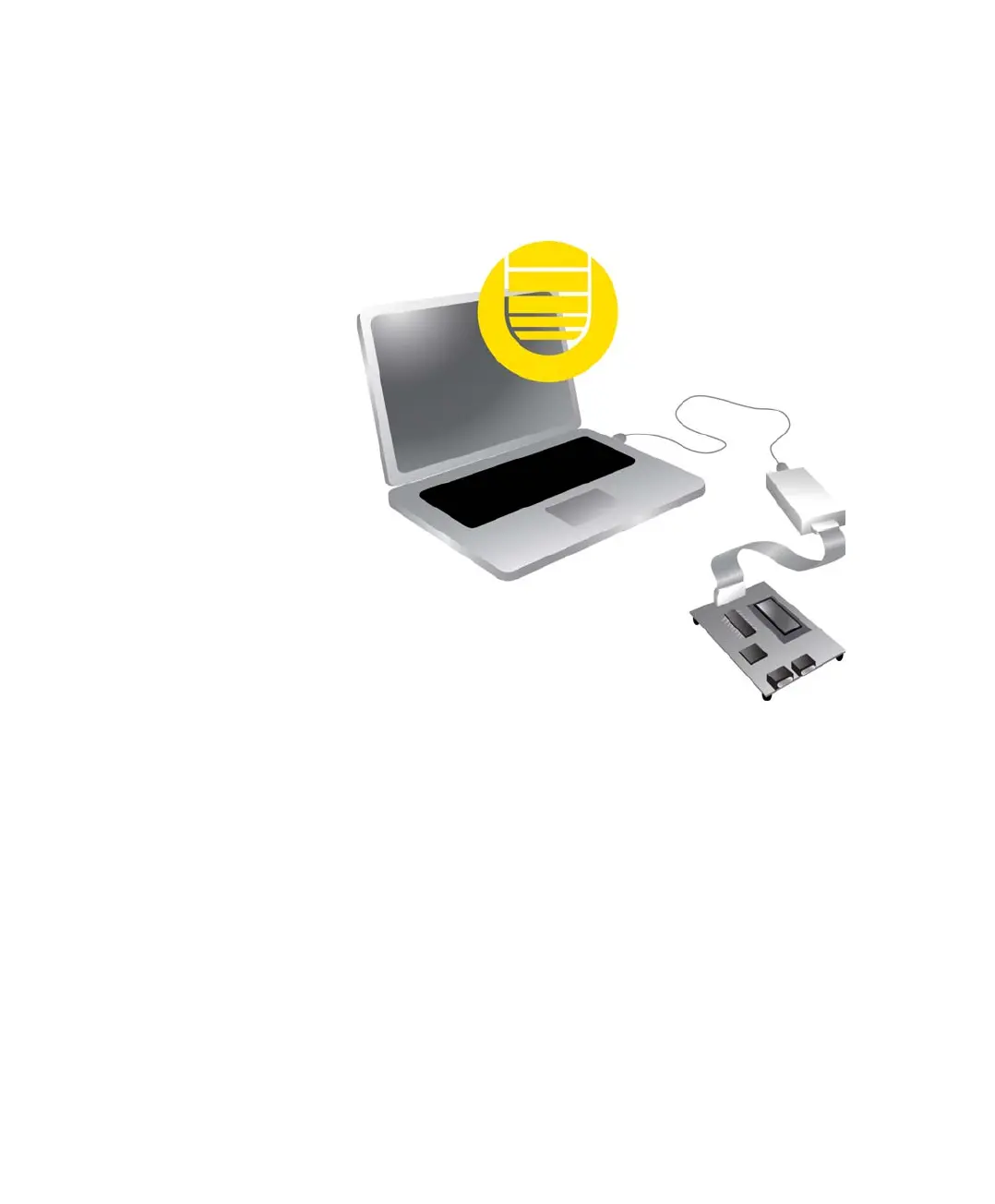
I-jet Trace CM connects to the target board via a MIPI-20 header. By default, I-jet Trace
A/R/M connects to the target via the Mictor-38 headers, but it also supports the MIPI-20
headers. The probes connect to the host computer via the USB port.
I-jet Trace streams the program counter, variables, and power measurement data to the
host computer to provide a view into program execution in real time. Besides the typical
JTAG debugging, I-jet Trace is capable of providing power to the target board, and
measuring it with sufficient accuracy to provide a power profile during program
execution in real time. This feature is referred to as power debugging.
For debugging Cortex devices, I-jet Trace also supports the SWO (Serial Wire Output)
feature, which can be used for tracing the program execution and tracking variables at
predefined points in your code.
The I-jet Trace in-circuit debugging probe is also referred to as a debug probe, debug
adapter, or JTAG in-circuit emulator by different tool vendors.
REQUIREMENTS
I-jet Trace needs to be controlled by the IAR C-SPY® Debugger which comes with the
IAR Embedded Workbench® IDE.
C-SPY debugger
C-SPY driver
USB connection
I-jet Trace
MIPI-20 or
Mictor-38