AFE1_AFE2-1:1
I-scope
59
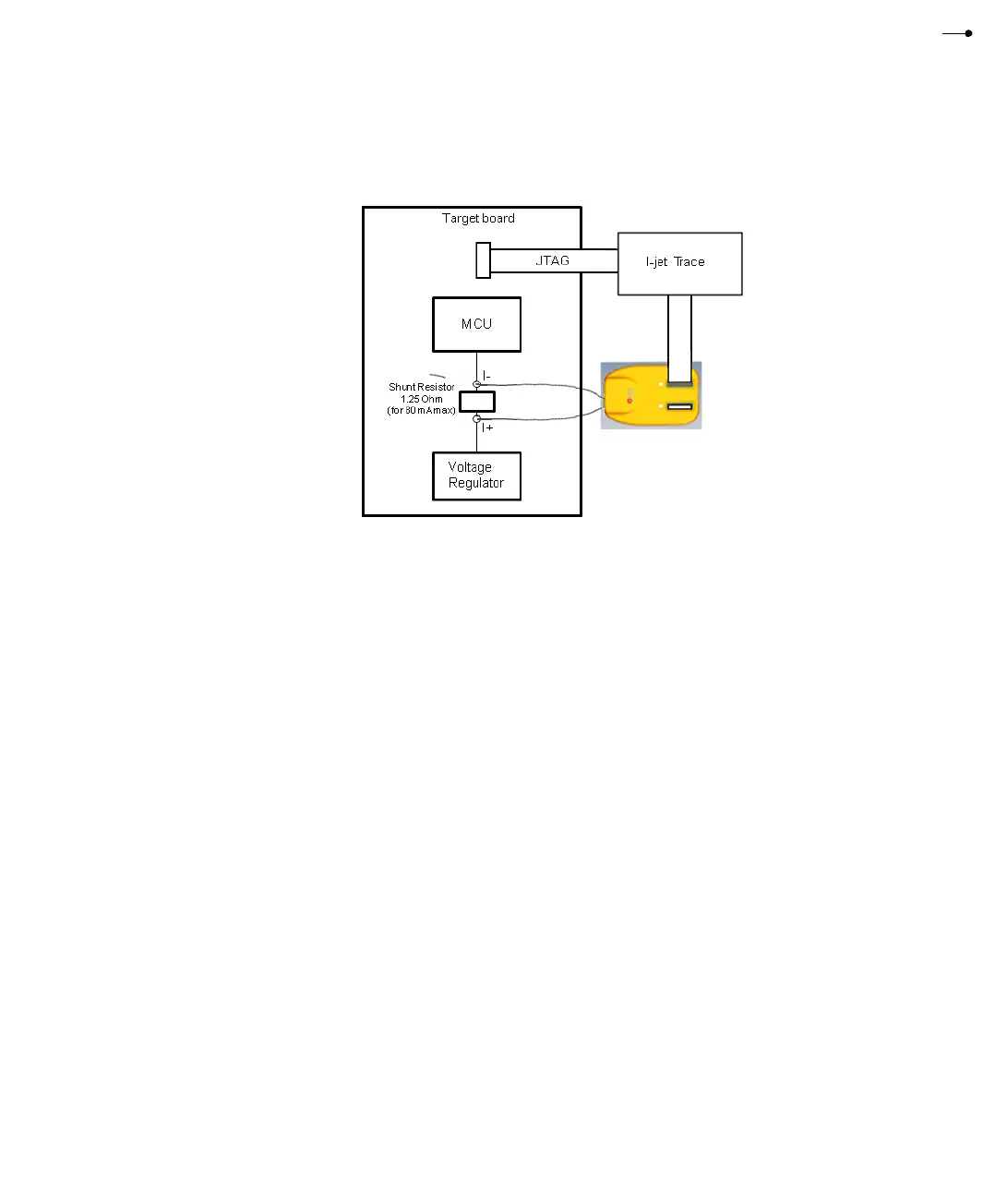
This figure shows how I-scope is connected to I-jet Trace and to the target board:
Many hardware engineers add small shunt resistors to the board to measure (using a
digital voltmeter) the currents taken by specific logic blocks or devices. This method is
mainly used in early stages of development. The shunt resistors are placed in series with
the power rail to be measured and they need to be small enough not to drop too much
voltage to make the logic block or MCU operate outside of its minimum voltage
requirements. For most MCUs, the power rails are specified within 100 mV of their
normal Vdd values and that is why I-scope is designed to work with shunt resistors that
will provide up to 100 mV voltage drop.
The calculation of the shunt resistor value is very simple. Assuming that the MCU's
maximum operating current at the selected clock speed and all peripherals enabled is
80 mA, Ohm's law will give the value for the shunt resistor as follows:
R = V/I = 0.1 V/0.08 A = 1.25 Ohm
Based on this example, the dynamic range of the power probe would be from
approximately 20 uA (80 mA/4096) to 80 mA.
It is recommended to use 1% (or better) resistors to get good accuracy in the
measurements. If the calculated value does not match the standard resistor value, select
the next smaller value. In our example, the next smaller standard resistor value is
1.24 Ohm.
Larger resistor values can be used, but I-scope will hit its maximum allowed value at
110 mV and anything over this will be cut off. So if you want to measure some low-level
currents, you can use much bigger shunt resistors to get better resolution. Make sure that
the MCU Vdd line does not drop below the minimum allowed by the manufacturer when