INSTALLATION AND OPERATION INSTRUCTIONS
1-24
SL 35-199, SL 45-260 MODULATING GAS BOILERS
Check valves or thermal traps should be used to isolate both the supply and
returnpipingforeachload-toavoidthermalsiphoningandreverseow.
Toensureadequatewaterowthroughtheboilerunderhigh-head/single
zone space heating conditions, a pressure activated bypass or other means of
bypassmustbeusedonanyloadwheretheowratemightdropbelowminimum
requirements (6 USgpm).
For further information and details, consult our Application Notes – which provide
detailonspecicsingleandmultipleboilerapplications“Piping”, “Wiring” and
“Settings”. (available at www.ibcboiler.com or from your IBC Representative).
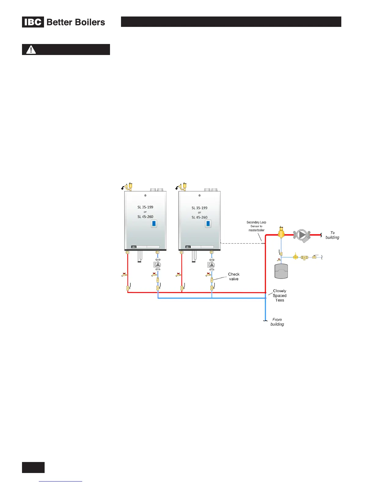
MULTIPLE BOILER PIPING - BENEFITS AND INSTALLATION RULES
Multiple IBC boilers can be installed in a single heating system to provide
redundancy, increased output, and greater heating plant turn-down capabilities.
Primary/Secondary piping must be employed, and each boiler must be installed
with its own pump as illustrated below. This approach provides constant head
andowateachboiler,regardlessofowvariationsinthemainbuildingloop.
Each boiler will control its own pump, turning it off or on when heat is required.
This approach saves electricity by reducing the pumping power required as load
conditions are reduced. One boiler control is set up as a “Master” boiler, and up
to 23 additional boilers can be added to the system as “Subordinate” boilers by
connecting a twisted pair of wires between the boilers. No additional controls are
needed.
Checkvalvesaretobeusedineachboilerspipingtopreventreverseowwhen
the boiler is off.
For further information and details, consult our Application Notes – which provide
detailonspecicsingleandmultipleboilerapplications“Piping”, “Wiring” and
“Settings”. (available at www.ibcboiler.com or from your IBC Representative).
Figure 28: Multiple boiler piping concept
NOTE
For further information and
details regarding Multiple
Boiler application, consult
our Technical Notes - Multiple
Boiler Systems. These notes
provide necessary detail on
specic single and multiple
boiler applications “Piping”,
“Wiring” and “Settings”.
(available at www.ibcboiler.
com or from your IBC
Representative).

 Loading...


