IBIS
GmbH
SiViB
Record 1500 / Record Control Manual Page 9
IBIS
Ingenieurbüro für Instandhaltungs- und Schwingungsmeß-Systeme GmbH
Reinheimer Str. 17, 64846 Groß-Zimmern, Germany; www.ibis-gmbh.de
Tel. +49 6071/42222, Fax +49 6071/71707, Email: info@ibis-gmbh.de
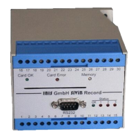
Terminals of instruments for eddy current probes
(Type 1532 for 2 eddy current probes and 1 accelerometer)
1 + 24 V DC
2 Ground 24 VDC
3 Accelerometer 1 Signal
4 Accelerometer 1 Ground
5 Alarm A
6 Alarm B
7 Alarm C
8 Alarms Set Input (Set 1)
9 Machine Speed Input (1 pulse per rev)
10 +24 V DC Supply for alarm outputs
11 Ground alarms
12 Option Analog Out 0 – 10 Volt for mm/s for input 1
13 Option Analog Out 0 – 10 Volt for gSE for input 1
14 Ground for analog outputs
15 Ground for analog outputs
16 (1
upper
row)
Eddy current probe 1 signal
17 Ground for eddy current probes
18 Eddy current probe 1 signal
19 Ground for eddy current probes
20 Supply for eddy current probes -24Volts max 40 mA
21 ECP1 Analog output 0-10 Volts DC for position
22 ECP1 Analog output 0-10 Volts DC for vibration
23 Out Ground (for analog outputs)
24 ECP1 Analog output 0-10 Volts DC for position
25 ECP1 Analog output 0-10 Volts DC for vibration
26 DIG IN 1 / Event enable
27 DIG IN 4 (store)
28 DIG GND
29 CAN Ser + (Option)
30 CAN Ser – (Option)
Description
Terminals 1 to 15 and 27 to 30 are equal to those on insruments for accelerometers. Please refer to
the description above for further explanations.
16 an 18 Signal input for eddy current probes.
17 and 19 Ground for eddy current signal inputs. Attention: do not connect to other ground ternials!
20 Output for supply voltage -24 Volts, max. 40 mA for oscillator/demodulator (sometimes called
proximitors or drivers). The corresponding ground terminals are 17 and 19. Attention: this supply is not
short-circuit proof!
21 and 24 Analog outputs 0 – 10 Volts for the static (position) component of the probe signal.
22 and 25 Analog outputs 0 – 10 Volts for the dynamic (vibration) component of the probe signal.
 Loading...