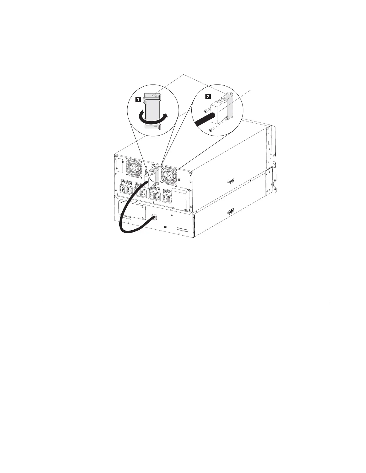
4. To provide strain relief and a secure connection for the extended battery module
power cord, rotate the extended battery module connector cover on its side and
position it under the extended battery module power cord 1.
Extended battery
module power cord
Extended battery
module connector cover
5. Secure the extended battery module connector cover to the UPS rear panel by
using the screws 2 that you removed in step 2 on page 12.
To remove the extended battery module power cord from the UPS, remove the two
screws that connect the extended battery module connector cover to the UPS.
Then, squeeze the two clamps on the sides of the plug and pull the plug out of the
extended battery module connector.
Completing the installation
To complete the installation of the UPS, complete the following steps:
1. If you are installing the IBM UPS Manager software, connect a computer to the
UPS by using one of the communication cables that come with the UPS. For
more information, see “Installing the UPS Manager software” on page 43.
2. If the rack cabinet has conductors for grounding or bonding of ungrounded
metal parts, connect the ground cable (purchased separately) to the ground
bonding screw. For the location of the ground bonding screw, see “Rear view of
the UPS” on page 9.
3. If an emergency power-off (disconnect) switch is required by local codes, see
“Installing the remote emergency power-off” on page 14 to install the remote
emergency power-off switch before you turn on the UPS.
4. Connect the devices that you want to protect to the applicable UPS output
receptacles. Do not turn on the devices. For information about load segments,
see “Configuring load segments” on page 38.
Chapter 2. Installing the uninterruptible power supply 13

 Loading...


