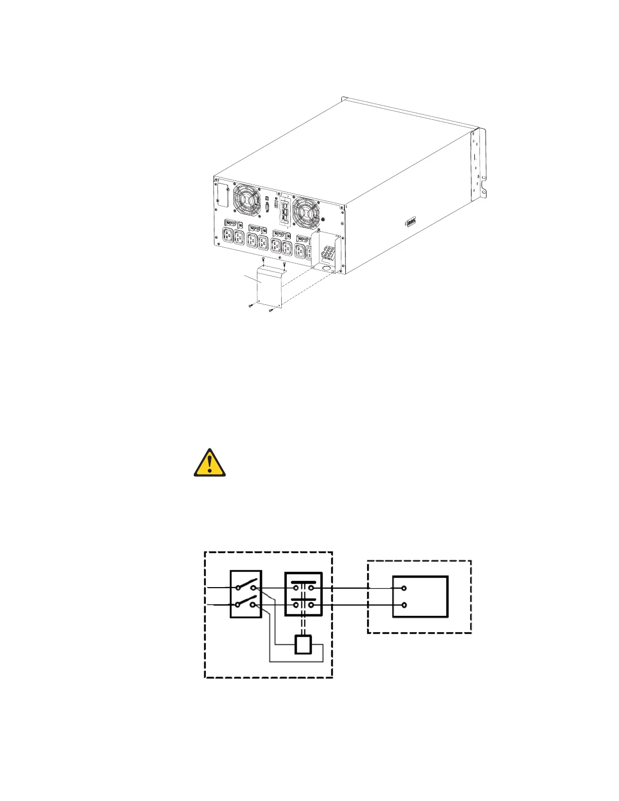
2. Remove the four screws that secure the terminal block cover to the UPS. Save
the screws.
Input terminal
block cover
3. Punch a hole in the terminal block cover for the input conduit, using a round
knockout punch or similar device. The hole must accommodate a 19 - 25.4 mm
(0.75 - 1 in.) Intermediate Metal Conduit (IMC).
4. Pull the input wire through the conduit, leaving approximately 0.5 m (2 ft) of
exposed wire. Attach a flexible metal fitting to the end of the conduit.
5. Insert the conduit through the wiring access entry and attach the conduit fitting
to the panel. Strip 1.5 cm (0.5 in.) of insulation from the end of each incoming
wire.
6.
CAUTION: The UPS does not have an automatic protection device against
current backfeed. Install an external isolating device as shown in the following
illustration. Check for hazardous voltage between all terminals before operating
on this circuit.
External distribution panel
Uninterruptible power supply
B
Q
T
N/L2
L/L1
Coil remote switch
Magneto-thermal input main switch
AC contactor rated 208 - 240 V, 68 A; 220 -
240 Vac, 68 A; or 220 - 240 Vac, 80 A
Neutral/L2
L1 Line input
Q
L/L1
N/L2
T
B
L/L1
N/L2
L/L1
N/L2
Chapter 2. Installing the uninterruptible power supply 17

 Loading...


