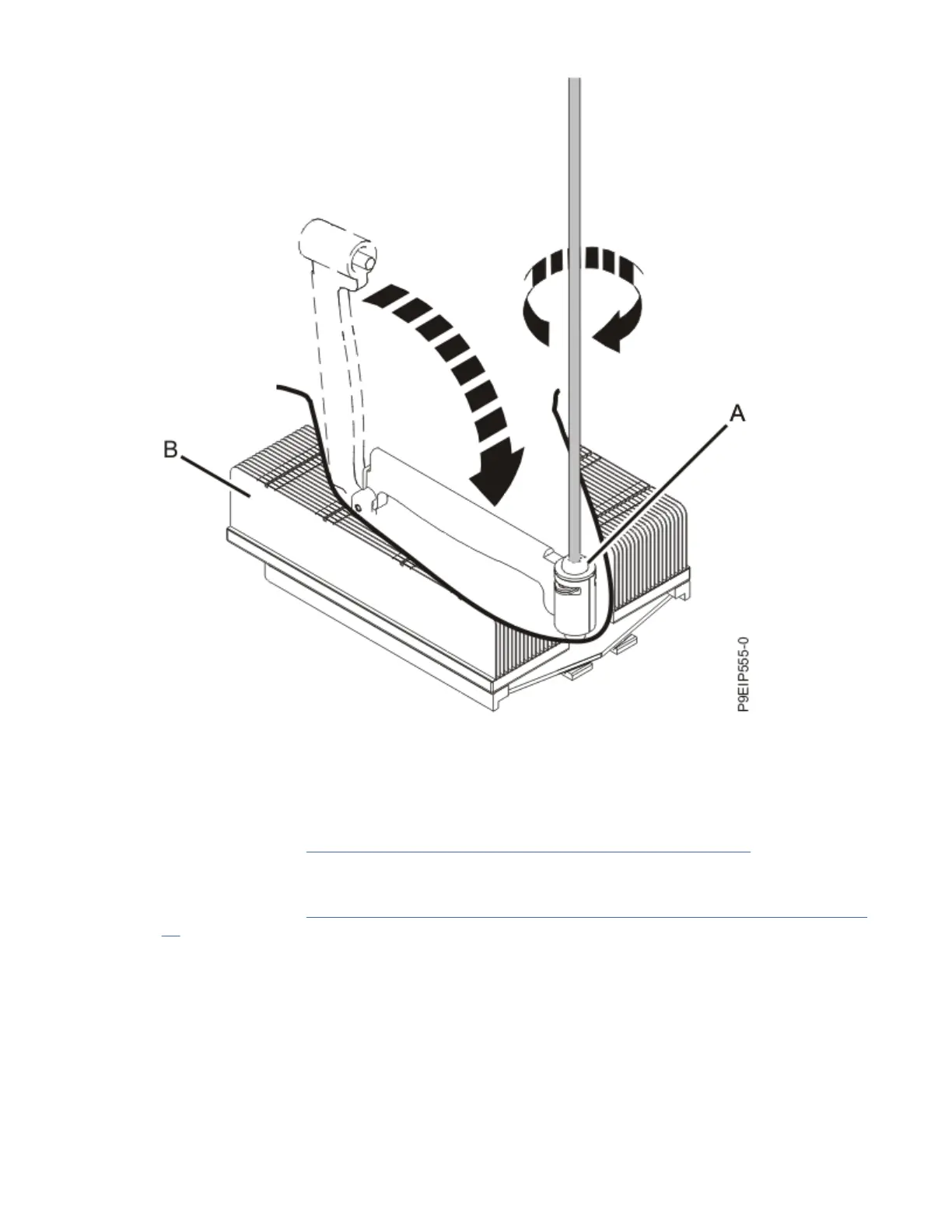
Figure 81. Tightening the load arm screw
The following steps move the remaining parts from the old system backplane to the new system
backplane:
21. Move the memory DIMMs from the old system backplane to the corresponding location on the new
system backplane.
For instructions, see “Removing and replacing memory in the 7063-CR2” on page 21.
22. Move the TPM card from the old system backplane to the corresponding location on the new system
backplane.
For instructions, see “Removing and replacing the trusted platform module in the 7063-CR2” on page
89.
23. If applicable, move the PCIe adapter from the old system backplane to the corresponding location on
the new system backplane.
a) Remove the screw that secures the PCIe adapter to the system backplane.
64
Power Systems: Servicing the IBM Power Systems HMC (7063-CR2)

 Loading...


