166 IBM Power 770 and 780 (9117-MMD, 9179-MHD) Technical Overview and Introduction
This improvement in the ECC word algorithm replaces the redundant bit steering used on
POWER6 systems.
The Power 770 and 780, and POWER7 high-end machines (such as 9119-FHB), have a
spare DRAM chip per rank on each DIMM that can be set up as a spare. Effectively, this
protection means that on a rank basis, a DIMM pair can detect and correct two and
sometimes three chipkill events and still provide better protection than ECC, explained in
the previous paragraph.
Hardware scrubbing
Hardware scrubbing is a method used to deal with intermittent errors. IBM POWER
processor-based systems periodically address all memory locations. Any memory
locations with a correctable error are rewritten with the correct data.
CRC
The bus that is transferring data between the processor and the memory uses CRC error
detection with a failed operation-retry mechanism and the ability to dynamically retune bus
parameters when a fault occurs. In addition, the memory bus has spare capacity to
substitute a spare data bit-line, for that which is determined to be faulty.
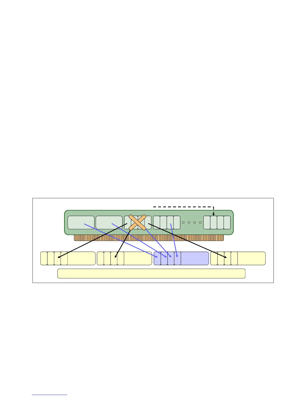
Chipkill
Chipkill is an enhancement that enables a system to sustain the failure of an entire DRAM
chip. Chipkill spreads the bit lines from a DRAM over multiple ECC words so that a
catastrophic DRAM failure does not affect more of what is protected by the ECC code
implementation. The system can continue indefinitely in this state with no performance
degradation until the failed DIMM can be replaced. Figure 4-2 shows an example of how
Chipkill technology spreads bit lines across multiple ECC words.
Figure 4-2 Chipkill in action with a spare memory DRAM chip on a Power 770 and Power 780
POWER7and POWER7+ memory subsystem
The POWER7 and POWER7+ chip contains two memory controllers with four channels per
memory controller. Each channel connects to a single DIMM, but because the channels work
in pairs, a processor chip can address four DIMM pairs, two pairs per memory controller.
The bus that transfers data between the processor and the memory uses CRC error detection
with a failed operation-retry mechanism and the ability to dynamically retune bus parameters
when a fault occurs. In addition, the memory bus has spare capacity to substitute a spare
data bit-line, for that which is determined to be faulty.
ECC word ECC word ECC word ECC word
Chipkill
DRAM sparing
Spare
memory
chip
Scattered memory chip bits across separate ECC words for Chipkill

 Loading...

