Chapter 2. Architecture and technical overview 53
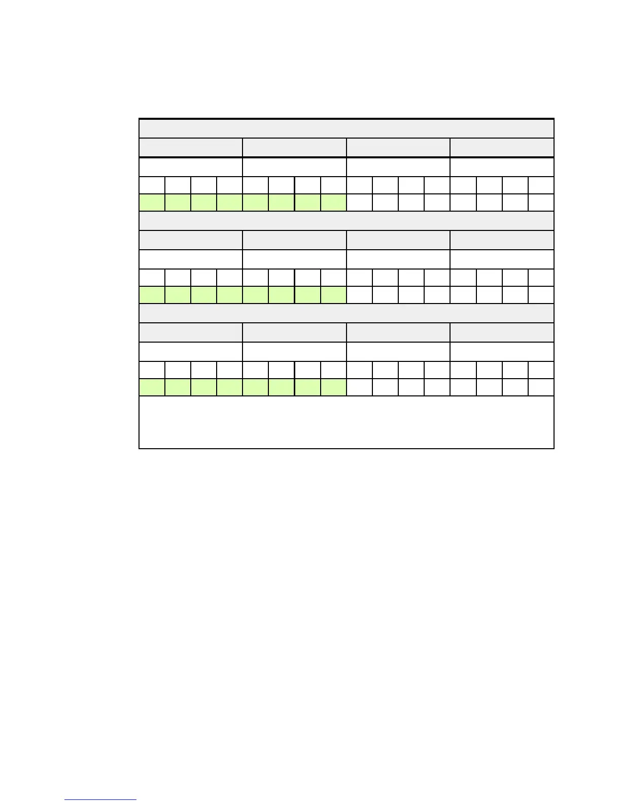
Table 2-5 shows the optimal placement of each DIMM-quad within a three-enclosure system.
Each enclosure
must have at least two DIMM-quads installed.
Table 2-5 Optimum DIMM-quad placement for a three-enclosure system
Enclosure 1
CPU 1 CPU 3 CPU 4 CPU 2
Memory controller Memory Controller Memory controller Memory controller
J1A J2A J3A J4A J5A J6A J7A J8A J1B J2B J3B J4B J5B J6B J7B J8B
Q1 Q1 Q2 Q2 Q1 Q1 Q2 Q2 Q7 Q7 Q12 Q12 Q7 Q7 Q12 Q12
Enclosure 2
CPU 1 CPU 3 CPU 4 CPU 2
Memory controller Memory controller Memory controller Memory controller
J1A J2A J3A J4A J5A J6A J7A J8A J1B J2B J3B J4B J5B J6B J7B J8B
Q3 Q3 Q4 Q4 Q3 Q3 Q4 Q4 Q8 Q8 Q11 Q11 Q8 Q8 Q11 Q11
Enclosure 3
CPU 1 CPU 3 CPU 4 CPU 2
Memory controller Memory controller Memory controller Memory controller
J1A J2A J3A J4A J5A J6A J7A J8A J1B J2B J3B J4B J5B J6B J7B J8B
Q5 Q5 Q6 Q6 Q5 Q5 Q6 Q6 Q9 Q9 Q10 Q10 Q9 Q9 Q10 Q10
Quads Q1 and Q2 must be identical to each other. Quads Q3 and Q4 must be identical to each other.
Quads Q5 and Q6 must be identical to each other.
Note: For maximum memory performance, the total memory capacity on each memory controller
must be equivalent.
 Loading...