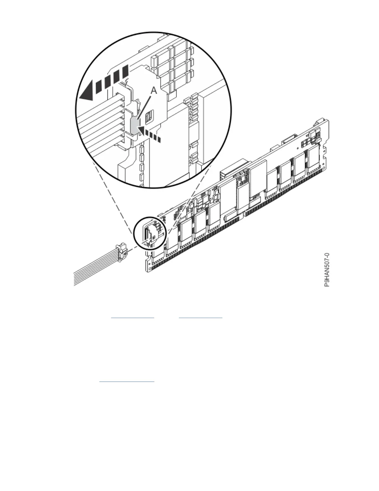
Figure 7. Disconnecting a BPM cable from the NVDIMM
e) Place the NVDIMM on an appropriate ESD surface.
f) Repeat steps “3.a” on page 7 through “3.e” on page 9 for any additional NVDIMMs.
4. Remove the backup power modules, if present. Otherwise, continue to the next step.
Note: The backup power module (BPM) is mounted in a standard drive carrier. The BPM is handled as
a drive in this procedure.
a) If your system has more than one BPM, record the location of both BPMs and decide which BPM
you want to remove rst.
b) Provide slack in the BPM cable by pulling the BPM cable forward about 5 cm (2 in) in the direction
shown in Figure 8 on page 10.
Drive backplanes for the 5105-22E, 9008-22L, 9009-22A, 9009-22G, or 9223-22H
9

 Loading...


