A worn pawl
wi
II
be
notched and polished
at
point
"A".
ESCAPEMENT
PAWL
Figure
3.1
3.9
S.H.
CARRIER
RETURN
SPRING
CLUTCH
3.10
Under no circumstances should
the
carrier
return
spring
clutch
be
lubricated with
grease
or
oil.
The
only
recommendation made by Engineering for
lub-
ricafion
in
this
area
is
a
very
light
fi
1m
of oi I
to
be
placed
on
the
outside surface of
the
spring
clutch
to
prevent rust.
If
the
carrier
return spring
clutch
becomes
contam-
inated
with
grease
or
oil,
several
intennittent
car-
rier
return problems
wi
II
result.
1.
Uneven
LH
margin due
to
fai lure
of
spring
clutch
to
disengage on its
arbor.
2.
Sluggish
tab
or print escapement due
to
the
contamination not allowing
the
spring
clutch
to
fully
release
the
pinion.
3.
asci
lIating
carrier
motion when machine
is
idling due
to
contamination causing spring
clutch
to
engage
and
disengage erroneous Iy.
S.H.
MAIN SPRING
Effective with
I/O
Printer
SIN
4607171,
all
Se-
lectric
I/O
printers will incorporate a 100"
main-
spring.
The old
75"
mainspring, PN 1124519,
wi
II
no
long-
er
be
used. The new 100" mai nspri
ng,
PN
1164342,
wHI
be
avai lable for field replacement
and
is
di-
recty
interchangeable
with the old 75" mainspring.
The new
100" mainspring may easi
Iy
be
identified
by
the
"100" stamped on the rear
of
the
mai nspri
ng
cage.
This new spring
wi
II
add
greater
torque
to
the
car-
ri
er
escapement
and
tab
operati ons .
5-6
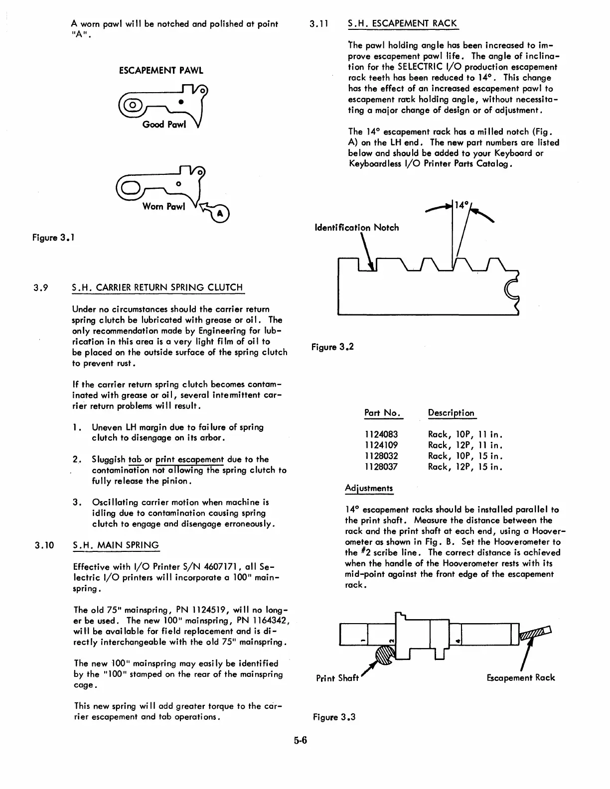
3.11
S.
H.
ESCAPEMENT
RACK
lhe
pawl holding
angle
has been increased
to
im-
prove escapement paw I Ii
fe.
The ang
Ie
of
inc
Ii
na-
tion for the
SELECTRIC
I/O
production escapement
rack
teeth
has been reduced
to
14°.
This
change
has
the
effect
of
an
increased escapement pawl
to
escapement rat:k holding
angle,
without
necessita-
ting a major
change
of design or
of
adjustment.
The 14° escapement rack has a
mi
lied notch (Fig.
A)
on
the
LH
end.
The new part numbers
are
listed
be
low
and
shou
Id
be
added
to
your Keyboard or
Keyboard less
I/O
Pri
nter
Parts
Cata
log •
Figure
3.2
Part
No.
Description
1124083
Rack,
lOP,
11
in.
1124109
Rack, 12P,
11
in.
1128032
Rack, lOP,
15
in.
1128037 Rack, 12P,
15
in.
Adjustments
14°
escapement racks should
be
installed
parallel
to
the
print
shaft.
Measure
the
distance
between
the
rack and
the
print shaft
at
each
end,
using a Hoover-
ometer as shown in
Fig.
B.
Set
the
Hooverometer
to
the
#2
scribe
line.
The
correct
distance
is
achieved
when
the
handle
of
the
Hooverometer rests with its
mid-point
against
the
front
edge
of
the
escapement
rack.
Escapement Rack
Figure
3.3

 Loading...


