Adjust Linkage
Keyboard Lock
No
Shift Clutch
o.·erdrives
4.2
Shift Link Bent
No
SHIFT
OR
ENTER
Yes
No
Interlock Adj ustment
4.3
Filter Shaft
4.6
Cycle
Shaft Overthrow 4
..
5
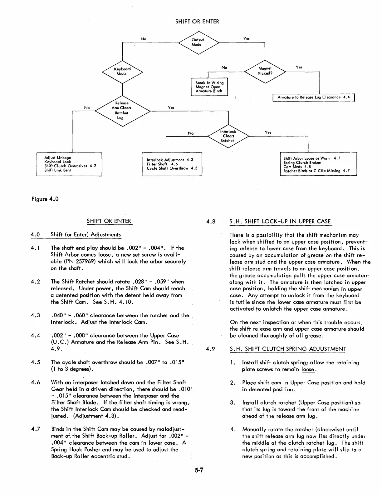
Figure
4.0
4.0
4.1
4.2
4.3
4.4
4.5
4.6
4.7
SHIFT OR
ENTER
Shift (or Enter) Adjustments
The
shaft
end
play
should
be
.002"
-
.004".
If
the
Shift Arbor comes loose, a new
set
screw is
avail-
able
(PN 257969) whi ch
will
lock
the
arbor
securely
on
the
shaft.
The Shift Ratchet should
rotate
.028"
-
.059"
when
released.
Under
power,
the
Shift Cam should
reach
a
detented
position with
the
detent
held
away
from
the
Shift
Cam.
See
S .
H.
4.
10
.
.
040"-
.060"
clearance
between
the
ratchet
and
the
interlock
..
Adjust
the
Interlock
Cam.
. 002" -
.OOS"
clearance
between
the
Upper
Case
(U.C.)
Armature
and
the
Release
Arm
Pin.
See
S.
H.
4.9.
The
cycle
shaft
overthrow should
be~
.007"
to
.015"
(l
to
3
degrees).
With
an
interposer
latched
down
and
the
Fi
Iter Shaft
Gear
held in a
driven
direction,
there
should
be
.010'
-
.015"
clearance
between
the
Interposer
and
the
Fi
Iter Shaft
Blade.
If
the
fi
Iter
shaft
timing is
wrong,
the
Shift Interlock Cam shou
Id
be
checked
and
read-
justed.
(Adjustment
4.3).
Binds in
the
Shift Cam
may
be
causled
by
maladjust-
ment
of
the
Shift Back-up Roller. Adjust for
.002"
-
.004"
clearance
between
the
cam in lower
case.
A
Spri
ng
Hook Pusher
end
may
be
used
to
adj ust
the
Back-up Roller
eccentric
stud.
4.S
4.9
5-7
No
Yes
Yes
Armature to
Release
Lug
Clearanc;-4A
J
Yes
-]
Shift Arbor Loose or Worn
4.
1
Spring
Clutch
Broken
Cam Binds
4.8
Ratchet Binds or C
Clip
Missing
4.7
S.
H.
SHIFT
LOCK-UP IN
UPPER
CASE
There
is
a possibi
lity
that
the
shift mechanism may
lock when
shifted
to
an
upper
case
position,
prevent-
ing
release
to
lower
case
from
the
keyboard.
This is
caused
by
an
accumulation
of
grease
on
the
shift
re-
lease arm stud
and
the
upper
case
armature.
When
the
shi ft re lease arm
trave
Is
to
an
upper
case
posi ti
on,
the
grease
accumulation
puHs
the
upper
case
armature
along with
it.
The
armature
is
then
latched
in upper
case
position,
holding
the
shift
mechanism in upper
case.
Any
attempt
to
un lock
it
from
the
keyboard
is
futi
Ie
since
the
lower
case
armature
must first
be
activated
to
un latch
the
upper
case
armature
.
On
the
next
inspection
or when this
trouble
occurs,
the
shift
release
arm and upper
case
armature
shou
Id
be
cleaned
thoroughly
of
all
grease
.
S.H.
SHIFT CLUTCH SPRING ADJUSTMENT
1.
Install shift
clutch
spring;
allow
the
retaining
plate
screws
to
remain loose.
2.
Place
shift cam in Upper Case position and hold
in
detented
position.
3.
Insta
1\
clutch
ratchet
(Upper Case posi
ti
on)
50
that
it~
lug is toward
the
front
of
the
machine
ahead
of
the
re lease arm
lug.
4.
Manually
rotate
the
ratchet
(clockwise) until
the
shift
release
arm lug now lies
directly
under
the
middle
of
the
clutch
ratchet
lug. The shift
clutch
spring
and
retaining
plate
will
slip
to
a
new positi on as this
is
accomplished.

 Loading...


