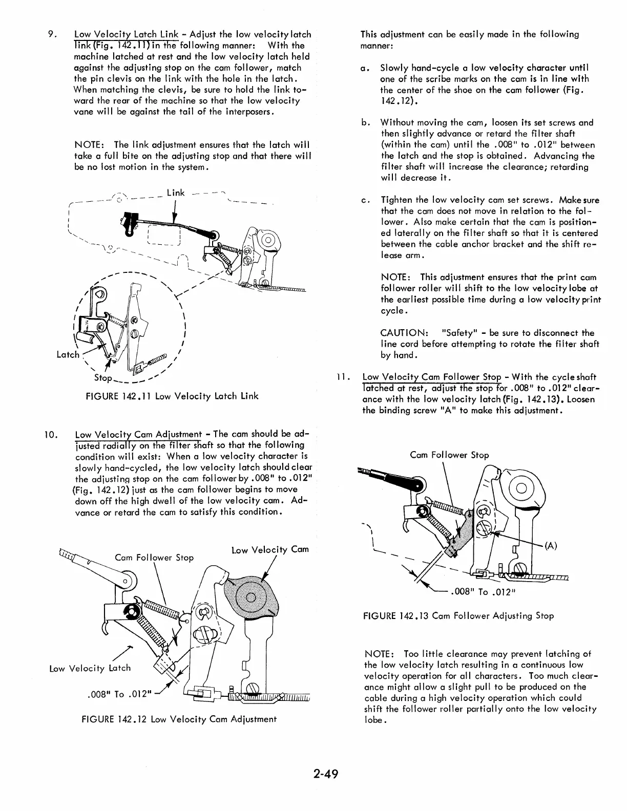
9.
Low
Velocity
Latch Link - Adjust the low
velocity
latch
link
(Fig.
142.11) in
the
following manner:
With
the
machine
latched
at
rest
and
the low
velocity
latch
held
a.gainst
the
adjusting
stop on the cam
follower,
match
the
pin
clevis
on
the
link
with
the
hole in
the
latch.
When
matching
the
clevis,
be sure
to
hold the link
to-
ward the
rear
of
the
machine
so
that
the low
velocity
vane
will be
against
the
tail
of
the
interposers.
NOTE: The
link
adjustment ensures
that
the
latch
will
take
a
fu
II
bi
te
on the
ad
j usti ng stop
and
that
there
wi II
be no lost motion in
the
system.
I
I
/
/
:~
'.
_ _ _ _ Link - - -
--.
\_,
/,"-
---
..................
,-"
............ J I
'-
'"
"
//
/
'('"
I ...... -..-:=:-lJ'I",_
\
\
I
I
I
,
\
I
Latch.
/'
" /
'"
Stop
_____
..,"
FIGURE
142.11
Low
Velocity
Latch Link
10.
Low
Velocity
Cam Adjustment - The cam should be
ad-
justed
radially
on
the
filter
shaft so
that
the
following
condition
will
exist:
When
a low
velocity
character
is
slowly
hand-cycled,
the
low
velocity
latch
should
clear
the
ad
i ustj ng stop on
the
cam foil ower by .008"
to
.012"
(Fig.
142.12) just as the cam follower begins
to
move
down
off
the
high dwell
of
the
low
velocity
cam.
Ad-
vance
or
retard
the
cam
to
satisfy this
condition.
/
Low
Velocity
Latch
.008"
To
.012"
FIGURE 142.12
Low
Velocity
Cam Adjustment
This adjustment
can
be
easily
made in the following
manner:
a.
Slowly
hand-cycle
a low
velocity
character
until
one
of
the
scribe
marks on
the
cam is in line
with
the
center
of
the
shoe on
the
cam follower
(Fig.
142.12) •
b.
Without
moving
the
cam,
loosen its
set
screws
and
then
slightly
advance
or
retard
the
fi Iter shaft
(within the cam) until
the
.008"
to
.01211
between
the
latch
and
the stop
is
obtained.
Advancing
the
filter
shaft will
increase
the
clearance;
retarding
will
decrease
it.
c.
Tighten the low
velocity
cam
set
screws.
Make sure
that
the
cam does not move in
relation
to
the
fol-
lower.
Also make
certain
that
the cam
is
position-
ed
laterall
y on
the
fi
I
ter
shaft so
that
it
is
centered
between
the
cable
anchor
bracket
and
the
shift
re-
lease
arm.
NOTE: This adjustment ensures
that
the
print cam
follower
roller
will shift
to
the
low
velocity
lobe
at
the
earliest
possible time during a low
velocity
print
cycle.
CAUTION:
"Safety"
- be sure
to
disconnect
the
line
cord before
attempting
to
rotate
the
filter
shaft
by
hand.
11
.
Low
Velocity
Cam Follower Stop -
With
the
cycle
shaft
latched
at
rest,
adjust
the
stop
for.
008"
to
.012
11
clear-
ance
with
the
low
velocity
latch
(Fig.
142.13).
Loosen
the
binding screw
IIA"
to
make this
adjustment.
2-49
Cam Follower Stop
FIGURE
142.13 Cam Follower Adjusting Stop
NOTE:
Too I
ittle
clearance
may
prevent
latching
of
the
low
velocity
latch
resulting
in a continuous low
velocity
operation
for
all
characters.
Too much
clear-
ance
might
allow
a
slight
pull
to
be produced on
the
cable
during a high
velocity
operation
which
could
shift
the
follower
roller
partially
onto
the low
velocity
lobe.

 Loading...


