Identifying the hardware components
The following graphics and descriptions identify the various hardware components
and port locations for the control enclosure and expansion enclosure.
Control enclosure components
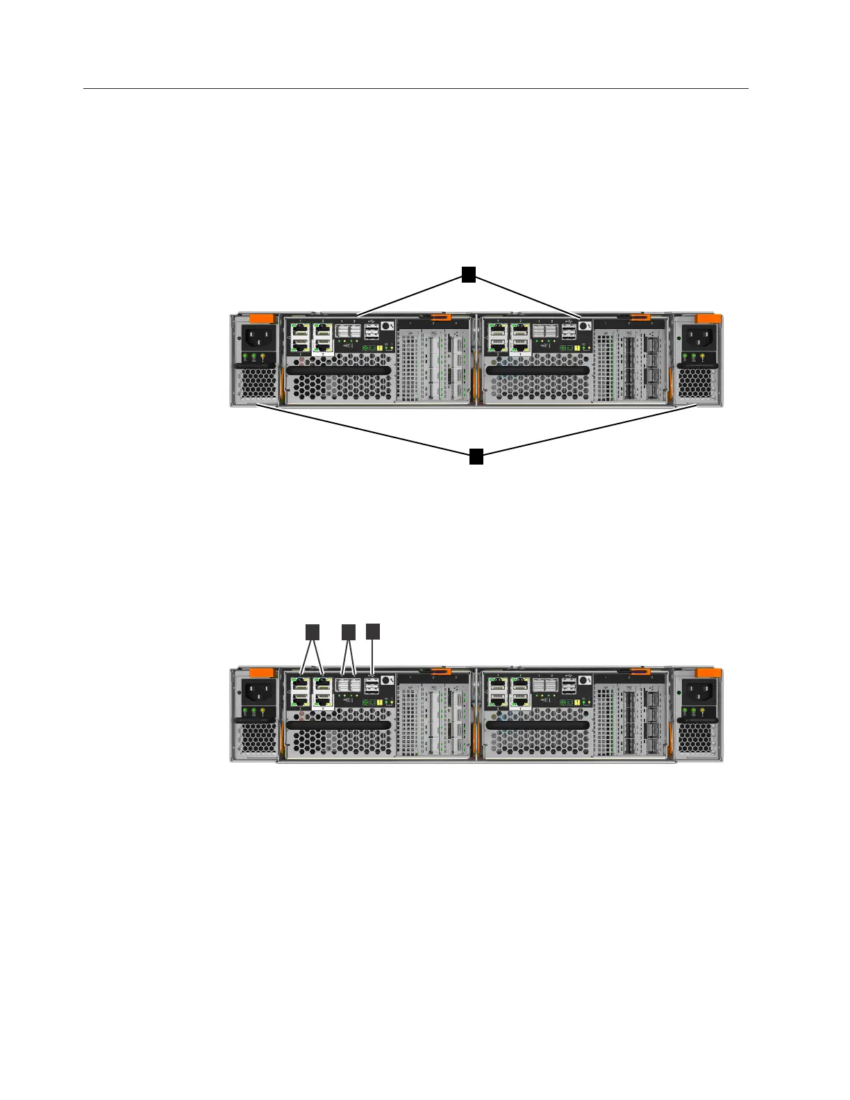
Figure 1 shows the rear view of a control enclosure and identifies the location of
the power supply units and node canisters.
v 1 Node canisters
v 2 Power supply units
Figure 2 shows the rear view of a Storwize V7000 control enclosure and identifies
the location of the ports.
v 1 USB ports. Each canister has two USB ports.
v 2 Ethernet ports. Each canister has four 1 Gbps Ethernet ports.
Port 1 Must be connected for system management. Can optionally be used for
iSCSI host connectivity.
Port 2 Optional. Can be used for iSCSI host connectivity or to provide an
alternative (redundant) management address.
Port 3 Optional. Can be used for iSCSI host connectivity.
Port T Technician port. Can be connected directly to a computer for service
access and system initialization.
fab10003
1
2
Figure 1. Rear view of a Storwize V7000 control enclosure
fab10004
2
3
1
Figure 2. Data ports in the rear of the control enclosure
6 Storwize V7000 Gen2: Quick Installation Guide

 Loading...


