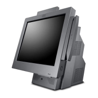
SurePOS 500 4846-XX5 Technical Reference
Page 38 of 63
24V +10%, -1% 3.0 A continuous, 5.0 A peak
Kybd and Mouse
(combined)
5V +5, -7% 2.26A
Cash Drawer (3A/3B) 24V 1A
5.3 Connector Pinouts
5.3.1 Customer Display Connector
Pin Connector Pin Connector
1 CD (carrier
detect)
9 +12 V dc
2 RXD (receive
data)
10 +5 V dc Main
3 TXD (transmit
data)
11 Dist_VFD present
4 DTR (data
terminal
ready)
12 DSR (data set ready)
5 Ground 13 RTS (request to send)
6 Ground 14 CTS (clear to send)
7 +5 V dc Main 15 RI (ring indicate)
8 +12 V dc
5.3.2 MSR connector
Pin Connector
1 +5 V dc Main
2 Serial Data In (TTL Level)
3 Serial Data Out (TTL Level)
4 Ground
5 MSR Present (low indicated MSR is present)
6 MSR Mode (low indicated keyboard wedge, high indicated RS-232)
7 Keyboare Enable (low enables keyboard data to the system
8 Keyboard Data (to system shipset)
9 Keyboard Clock (to system chipset)
10 Ground

 Loading...