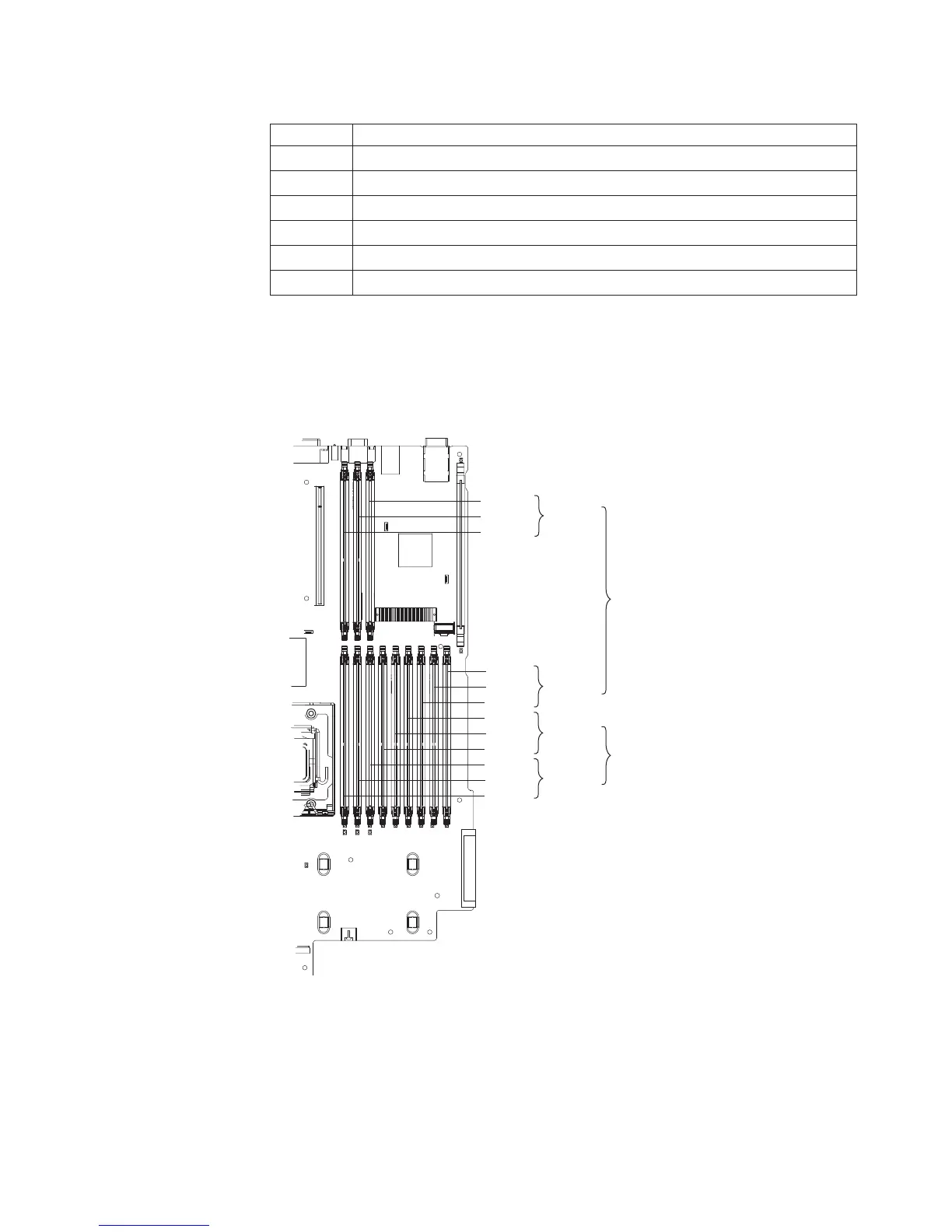
Table 2. DIMM installation sequence
Pair DIMM connectors
1 1 and 4
2 7 and 10
3 2 and 5
4 8 and 11
5 3 and 6
6 9 and 12
Note: When only one pair of DIMMs is installed in the server and the BIOS code
level is version 1.04 (GGE127A) or later, you can improve performance by
installing the DIMMs in connectors 1 and 7 instead of 1 and 4. However, because
the connectors in the pair are not on the same memory branch (see the following
illustration), Chipkill memory protection is disabled.
DIMM 1
DIMM 2
DIMM 3
DIMM 4
DIMM 5
DIMM 6
DIMM 7
DIMM 8
DIMM 9
Channel 0
Channel 1
Channel 2
DIMM 10
DIMM 11
DIMM 12
Channel 3
Branch 1
Branch 0
v Each DIMM in a pair must be the same size, speed, type, and technology to
ensure that the server will operate correctly.
v You can configure the server to use memory mirroring. Memory mirroring stores
data in two pairs of DIMMs simultaneously. If a failure occurs, the memory
controller switches from the active pair to the mirroring pair. See “Memory
mirroring” on page 15 for more information about memory mirroring and the
DIMM installation sequence that is required.
Chapter 2. Installing optional devices 13