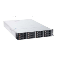
Installing the cover
To install the cover, place it into position and slide it forward.
Cover-release
latch
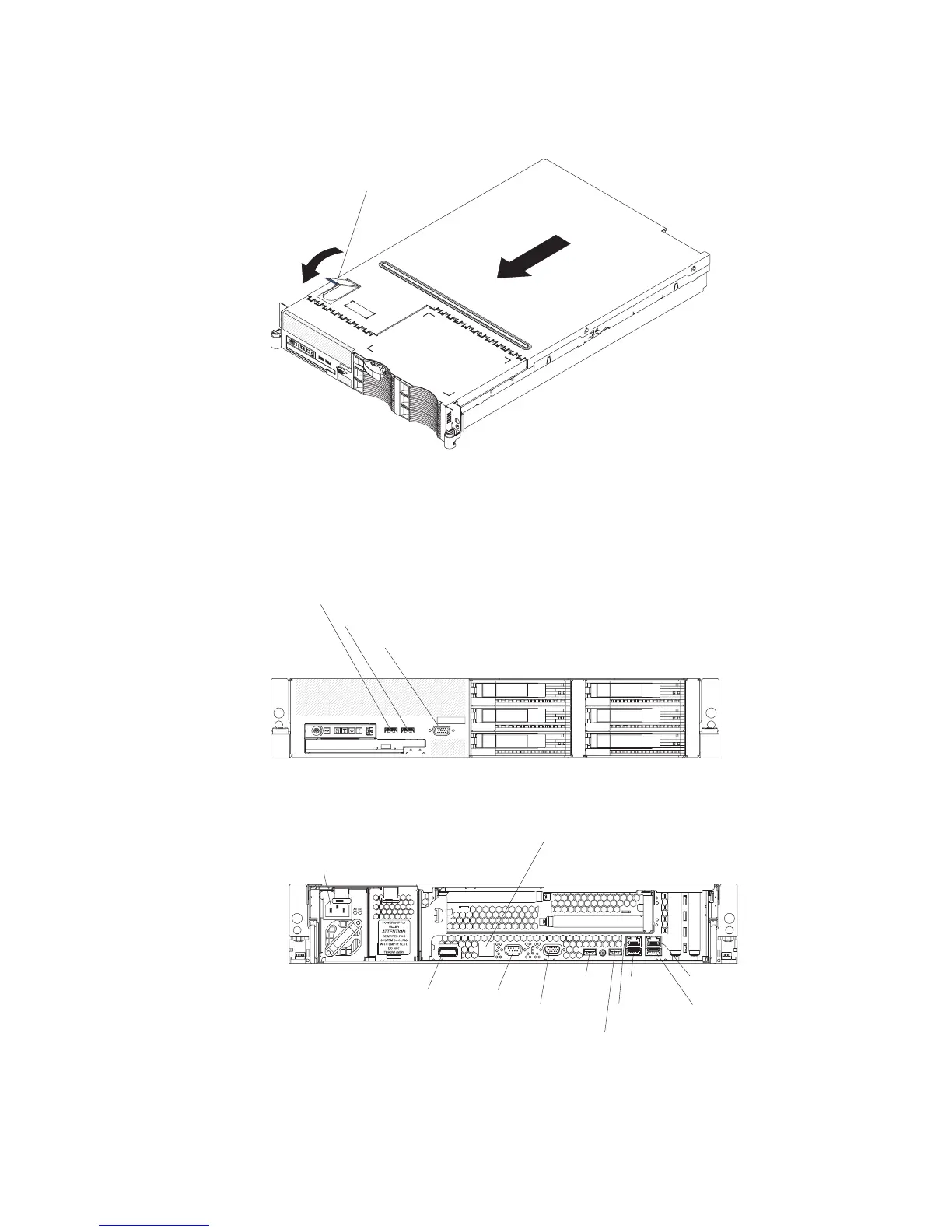
Connecting the cables
The following illustrations show the locations of the input and output connectors on
the front and rear of the server.
Front view
USB 5 connector
USB 6 connector
Video connector
Rear view
Power-cord
connector
SAS
connector
S-
Ethernet connector
ystems management
Serial
connector
Video
connector
USB 1
connector
USB 2
connector
USB 3
connector
USB 4
connector
Ethernet 2
connector
Ethernet 1
connector
Attention: In a dc power environment, only trained service personnel other than
IBM service technicians are authorized to connect or disconnect power to the dc
power supply. See the documentation that comes with each dc power supply for
instructions and an illustration of the dc power supply.
Chapter 2. Installing optional devices 33