Press the reset button to reset the server and run the power-on self-test (POST).
You might have to use a pen or the end of a straightened paper clip to press the
button.
The server is designed so that LEDs remain lit when the server is connected to a
power source but is not turned on, provided that the power supply is operating
correctly. This feature helps you to isolate the problem when the operating system
is shut down.
Diagnosing problems using light path diagnostics
LEDs in two locations on the server are available to help you diagnose problems
that might occur during installation. Use them in the following order:
1. Light path diagnostics panel - Look at this panel first. If a system error has
occurred, the system-error LED on the front of the light path diagnostics drawer
is lit. Slide the latch to the left on the front of the operator information panel to
access the light path diagnostics panel. Note any LEDs that are lit, and then
close the drawer.
2. LEDs on the system board - To identify the component that is causing the
error, note the lit LED on or beside the component.
Light path diagnostics LEDs
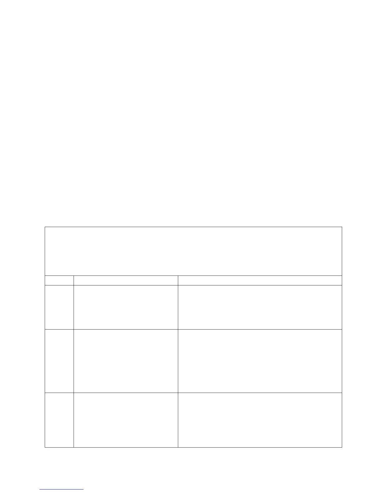
The following table describes the LEDs on the light path diagnostics panel, the
problems that they indicate, and actions to solve the problems.
v Follow the suggested actions in the order in which they are listed in the Action column until the problem
is solved.
v See the parts listing in the Problem Determination and Service Guide to determine which components are
customer replaceable units (CRU) and which components are field replaceable units (FRU).
v If an action step is preceded by “(Trained service technician only),” that step must be performed only by a
trained service technician.
LED Description Action
None, but
the
system-
error LED
is lit.
An error has occurred and cannot be
diagnosed, or the Advanced System
Management (ASM) processor on the
Remote Supervisor Adapter II SlimLine
has failed. The error is not represented
by a light path diagnostics LED.
Use the Configuration/Setup Utility program to check the
system-error log for information about the error.
OVER
SPEC
The power supplies are using more
power than their maximum rating.
1. Remove optional devices from the server.
2. Replace the failing power supply.
Attention: In a dc power environment, only trained
service personnel other than IBM service technicians are
authorized to connect or disconnect power to the dc power
supply and to remove and install a dc power supply. See
the documentation that comes with each dc power supply.
PS 1 The power supply in bay 1 has failed. Attention: In a dc power environment, only trained service
personnel other than IBM service technicians are authorized to
connect or disconnect power to the dc power supply and to
remove and install a dc power supply. See the documentation
that comes with each dc power supply.
1. Make sure that the power supply is correctly seated.
2. Replace the failed power supply.
Chapter 5. Solving problems 75