q
e
w
r
t
8
CONNECTION AND INSTALLATION
8-2
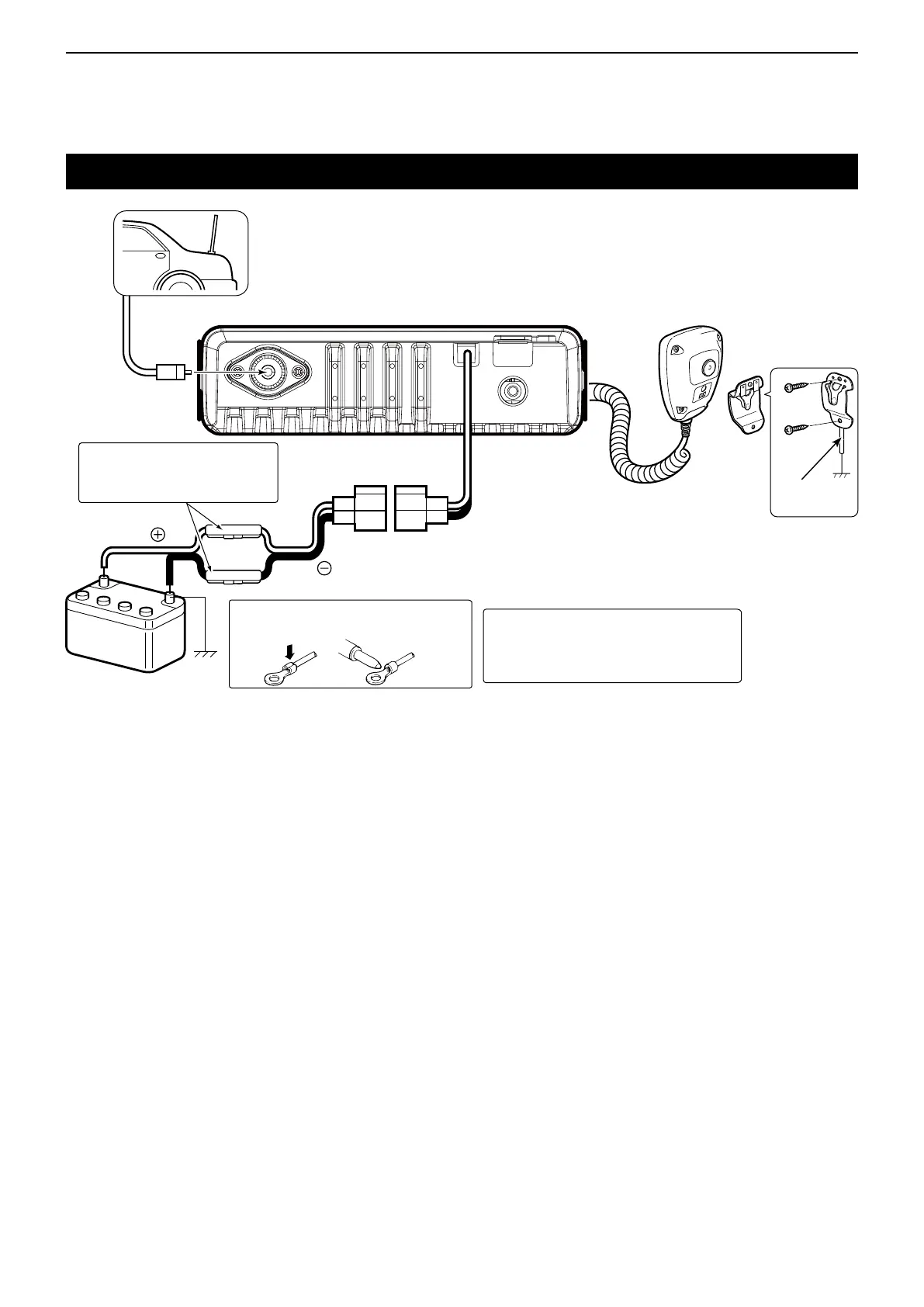
Rear panel connection
Antenna
Microphone
Black
Red
12 V or 24 V*
Battery
R WARNING! NEVER remove
the fuse holders from the DC
power cable.
NOTE: Use the terminals as shown
below for the cable connections.
Crimp
Solder
q ANTENNA CONNECTOR
Connect an antenna cable.
w HEADSET ADAPTER CONNECTOR
Connect an optional OPC-871A
headset adapter.
Ask your dealer for details.
e MICROPHONE HANGER
Connect the supplied
microphone hanger to the
vehicle’s ground to use the
microphone ON/OFF hook
functions.
t DC POWER RECEPTACLE
Connects to a 12 V or 24 V*
DC power source.
Pay attention to polarities.
R WARNING! NEVER connect the
transceiver to a power source of more
than 31.5 V DC. This could damage
the transceiver.
r EXTERNAL SPEAKER JACK
Connectan8Ωexternalspeaker
* The transceiver automatically
adjusts to the input voltage.
Microphone
hanger cable