10
CI-V INFORMATION
10-3
Command table
Cmd. Sub
cmd.
Data Description
00 See to the
right
Send operating frequency
for transceive*
1
01 See to the
right below
Send operating mode for
transceive*
1
03 See to the
right
Read operating frequency
04 See to the
right below
Read operating mode
05 See to the
right
Send operating
frequency*
1
06 See to the
right below
Send operating mode*
1
14 01 0000 to
0255
Send/read audio output
level
03 p. 10-4 Send/read squelch level
15 01 00 Read squelch status
(squelch close)
01 Read squelch status
(squelch open)
05 00 Read squelch status
(squelch close)
01 Read squelch status
(squelch open)
18 00 Turning OFF the
transceiver power
01 Turning ON the
transceiver power*
2
19 00 Read transceiver ID
1C 00 00 Send/read Transceiver’s
status (RX)
01 Send/read Transceiver’s
status (TX)
*
1
For only EXP, USA, and EUR versions.
*
2
When sending the power ON command (1801), the
command “FE” must be sent before the basic format.
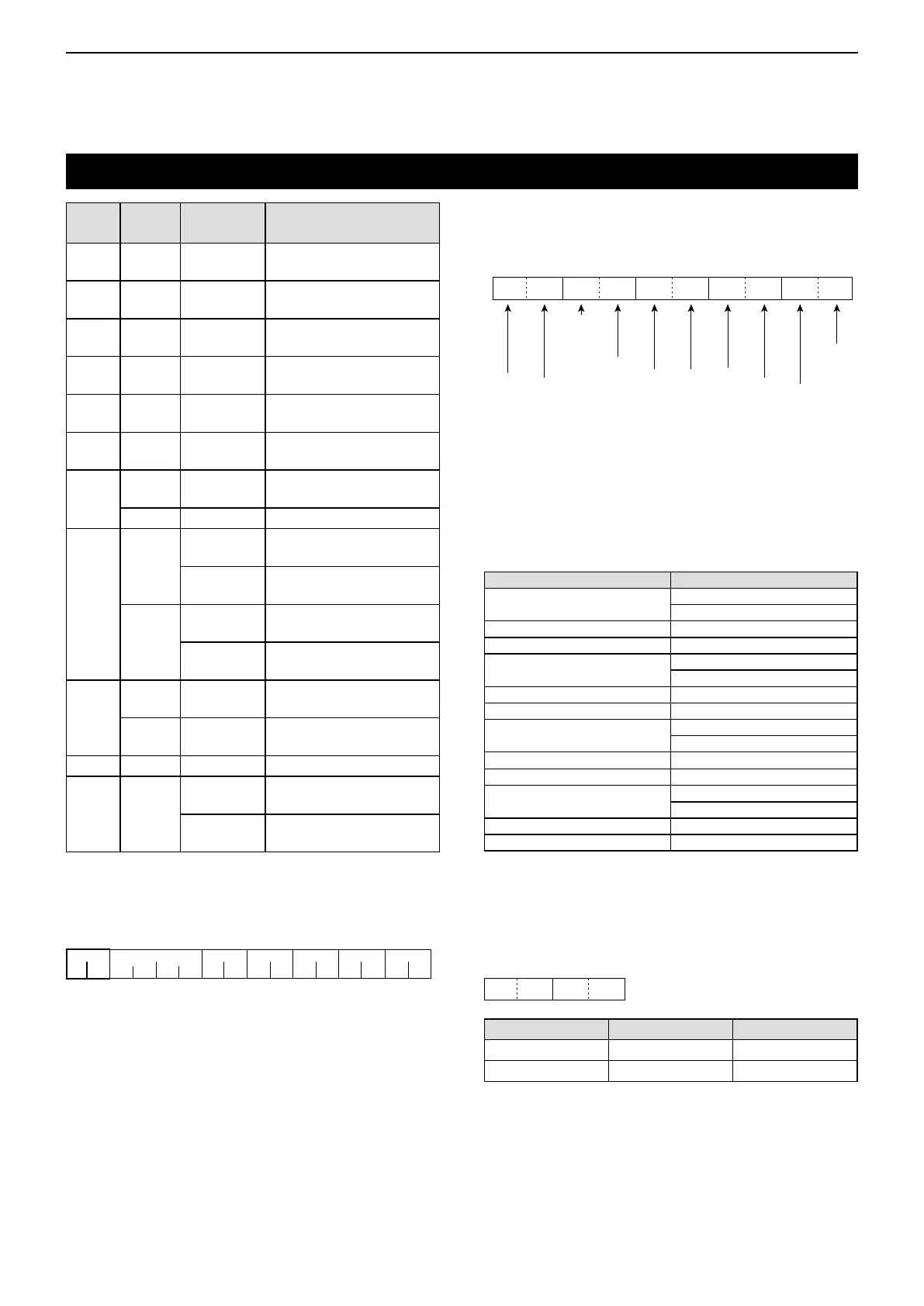
• 19200bps: 27 • 9600bps: 14 • 4800bps: 8
Example: When operating with 4800 bps
qwert
y
F
F E
29EFEE 1081
F
q Preamble code (xed) w Transceiver’s default address
e Controller’s default address r Command number
t Sub command number y End of message code (xed)
D Operating frequency setting
Command: 00, 03, 05
q
XXXXX
we
X
XX 10
10Hzdigit: 0, 3*, 6*
1 Hz digit: 0, 3*, 6*
1 kHz digit: 0, 1*, 3*, 5, 6*, 8*
100 Hz digit: 0, 3*, 6*
100 kHz digit: 0 to 9
10 kHz digit: 0 to 9*
10 MHz digit:0 to 9
1 MHz digit:0 to 9
1000 MHz digit: 0
(Fixed)
100 MHz digit: 1 (Fixed)
XXX0
qw
1kHz桁:0〜3
100Hz桁:0〜9
10Hz桁:0〜9
1Hz桁:0
(固定)
XX0 XXX
q* we
0 (fixed)
First digit: 0~7
Second digit: 0~7
Third digit: 0~7
Receive polarity: 0: Normal
1: Reverse
Transmit polarity: 0: Normal
1: Reverse
The frequency set by CI-V and the actual frequency
differs, as described in the table below.
The frequency set by CI-V Actual frequency
XXX. X00 XXX. X00 (AM)
XXX. X00 (AM Narrow)
XXX. X08 333* XXX. X10*
XXX. X16 666* XXX. X15*
XXX. X25 XXX. X25 (AM)
XXX. X30 (AM Narrow)
XXX. X33 333* XXX. X35*
XXX. X41 666* XXX. X40*
XXX. X50 XXX. X50 (AM)
XXX. X55 (AM Narrow)
XXX. X58 333* XXX. X60*
XXX. X66 666* XXX. X65*
XXX. X75 XXX. X75 (AM)
XXX. X80 (AM Narrow)
XXX. X83 333* XXX. X85*
XXX. X91 666* XXX. X90*
* For only 8.33 kHz channel spacing.
D Operating mode setting
Command: 01, 04, 06
X
X
Operating mode
q Mode w Filter setting
AM 02 01
AM-N 02 02