10
CI-V INFORMATION
10-2
CI-V data setting
You can control the transceiver with the Icom
Communications Interface-V (CI-V) commands.
Set the transceiver’s address, baud rate and
transceive functions. See page 7-6 for setting the
CI-V conditions using the Menu mode.
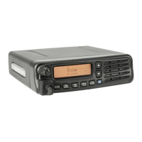
Connect the transceiver to a PC as shown below.
To use the OPC-478UC clOning cable and the OPC-
592 clOning cable adapter, you must rst install a
USB driver.
The driver and installation guide are supplied with the
cloning cable.
Read the guide carefully before installing the driver.
CI-V connection example
IC-A120/IC-A120E
To a USB port
USB cable
OPC-592
OPC-478UC
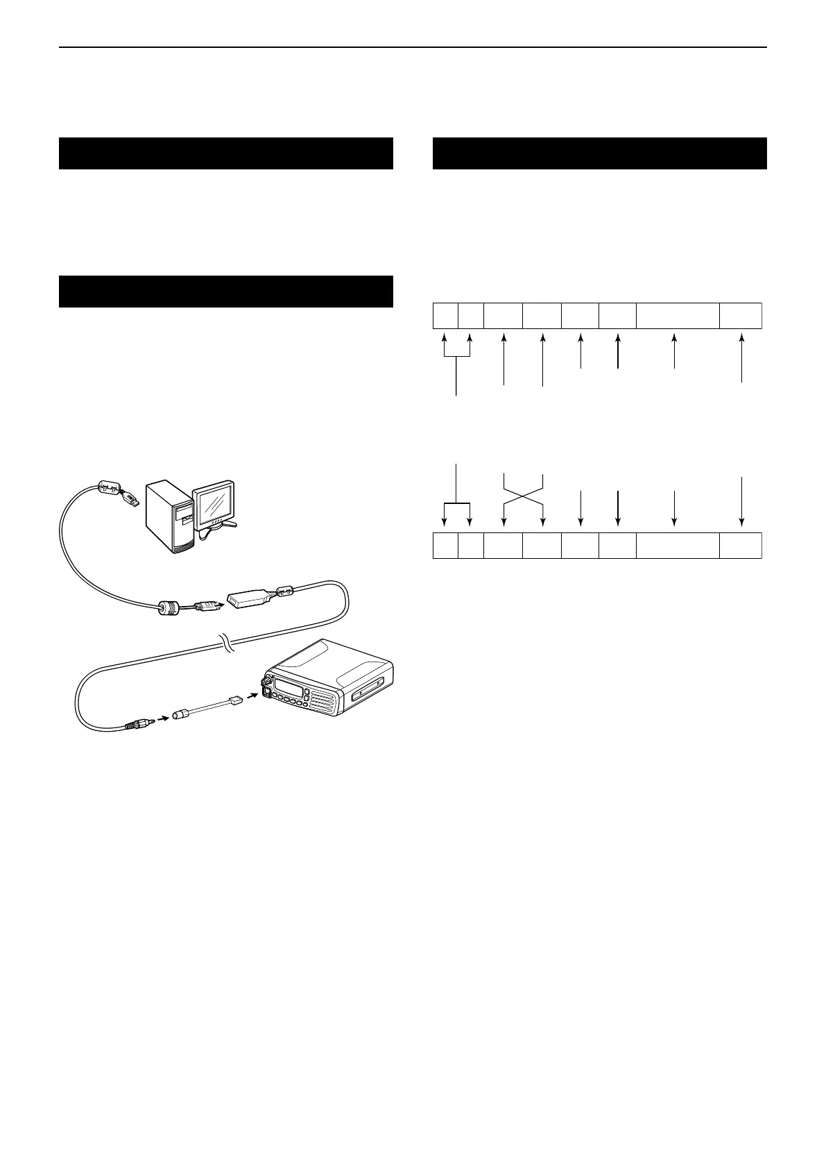
Data format
The CI-V system uses the following data formats.
Data formats differ, depending on the command
numbers. A data area or sub command is added to
some commands.
* The reply messages from the transceiver are the command
“FB” (OK) or “FA” (NG).
Controller to IC-A120/IC-A120E
FE FE 92 E0 Cn Sc Data area FD
Preamble
code
(fixed)
Transceiver’s
default address
Controller’s
default address
Command number
(see the command table)
Sub command number
(see the command table)
BCD code data such as
for frequency, memory
number entry
(see the data content description)
End of message
code
(fixed)
IC-A120/IC-A120E to controller
qwerty u
FE FE E0 92 Cn Sc Data area FD
qwer* ty u