IV
QUICK REFERENCE GUIDE
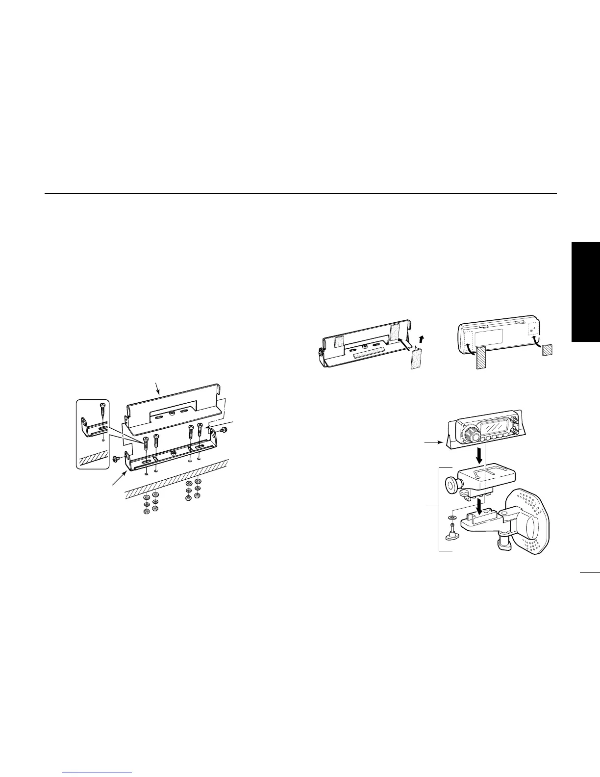
D Optional MB-58 installation
The optional MB-58
REMOTE CONTROLLER BRACKET
is avail-
able for separate installation.
qDrill 2 or 4 holes where the bracket is to be installed.
• Approx. 4 mm (
1
⁄8″) when using nuts; approx. 1–2 mm (
1
⁄16″)
when using self-tapping screws.
wInsert the supplied screws, bolts and washers through the
mounting base and tighten.
eAdjust the angle for the clearest view of the function dis-
play and tighten 2 screws when the mounting base is used.
rAttach the supplied Velcro pads (large) to the remote con-
troller and bracket.
tAttach the supplied Velcro pads (small) or rubber pad to
the bracket as shown below; then attach the remote con-
troller.
• When using the optional MB-65
 Loading...