4 - 5
The “FOR” voltage from the FILTER unit is applied to
IC1701c (pin 9) in the MAIN unit. The “POCV” voltage from
the D/A converter (IC3301, pin 2), determined by the RF
power setting, is applied to IC1701c (pin 10) as the refer-
ence voltage.
When the “FOR” voltage exceeds the “POCV” voltage, ALC
bias voltage from IC1701c (pin 8) controls the IF amplifiers
(Q151, Q502). This adjusts the output power to the deter-
mined level by the RF power setting until the “FOR” and
“POCV” voltages are equalized.
In AM mode, Q1705 turns ON and C1707, C1708 are con-
nected to the “FOR” voltage line to obtain an averaging ALC
operation. Q1706 turns ON and the “POCV” voltage is shift-
ed for 40 W AM output power (maximum) through R1730.
An external ALC input from the [ACC] socket or the [ALC]
jack is applied to the buffer amplifier (Q1703). External ALC
operation is identical to that of the internal ALC.
4-2-8 APC CIRCUIT (MAIN UNIT)
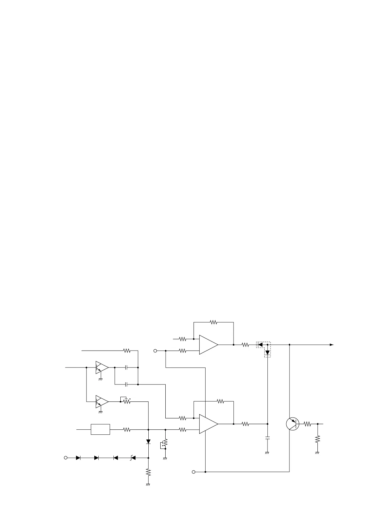
The APC (Automatic Power Control) circuit protects the
power amplifiers on the PA unit from high SWR and exces-
sive current.
A reflected wave signal appears and increases on the anten-
na connector when the antenna is mismatched. D3 of the
SWR detector circuit (L13, D2, D3) in the FILTER unit
detects the signal and applies it to IC1701b in the MAIN unit
as the “REF” signal. When the “REF” signal level increases,
IC1701b decreases the ALC line voltage via R1716 to acti-
vate the ALC.
For the current APC, the power transistor current is obtained
by detecting the voltage (“ICH” and “ICL”) which appear at
both terminals of a 0.012 Ω resistor (PA unit; R25). The
detected voltage is applied to the differential amplifier
(IC1701a, pins 2, 3). When the current of the final transistors
is more than 22 A, IC1701a controls the ALC line via D1705
to prevent excessive current flow.
4-2-9 TEMPERATURE PROTECTION CIRCUIT
(MAIN UNIT)
A cooling fan (CHASSIS; MF1) is activated while transmit-
ting or if the temperature of Q4 (PA unit) exceeds the preset
value.
While transmitting, PAT8 voltage is provided to MF1 via R30.
Thermistor R30 on the PA unit detects the temperature of
Q4. If the Q4 temperature is more than 50 C (122 F), R30
becomes very low impedance. Then TEMP signal from PA
unit is applied to the A/D converter section of the CPU (IC1,
pin 94) in the LOGIC unit as PATL signal. And the CPU out-
puts control signal to rotate the cooling fan at high speed via
the I/O expander (IC3301, pin 8) as FANV signal – even
when the transceiver condition has changed from transmit to
receive.
4-2-10 RF METER CIRCUIT (MAIN UNIT)
The “FOR” voltage from the FILTER unit is applied to the RF
meter amplifier (IC1751a, pin 2) via the ALC amplifier
(IC1701c). The amplified voltage is output from pin 1
(IC1751a) and then applied to the A/D converter section of
the CPU (IC1, pin 99) in the LOGIC unit.

 Loading...


