5 - 2
5-2 PLL ADJUSTMENTS
REFERENCE
FREQUENCY
VCO LOCK
VOLTAGE
1ST LO
OUTPUT
LEVEL
2ND LO
OUTPUT
LEVEL
BFO
OUTPUT
ADJUSTMENT
ADJUSTMENT ADJUSTMENT CONDITION
MEASUREMENT
VALUE
POINT
UNIT LOCATION UNIT ADJUST
1
2
3
1
2
1
2
1
1
2
3
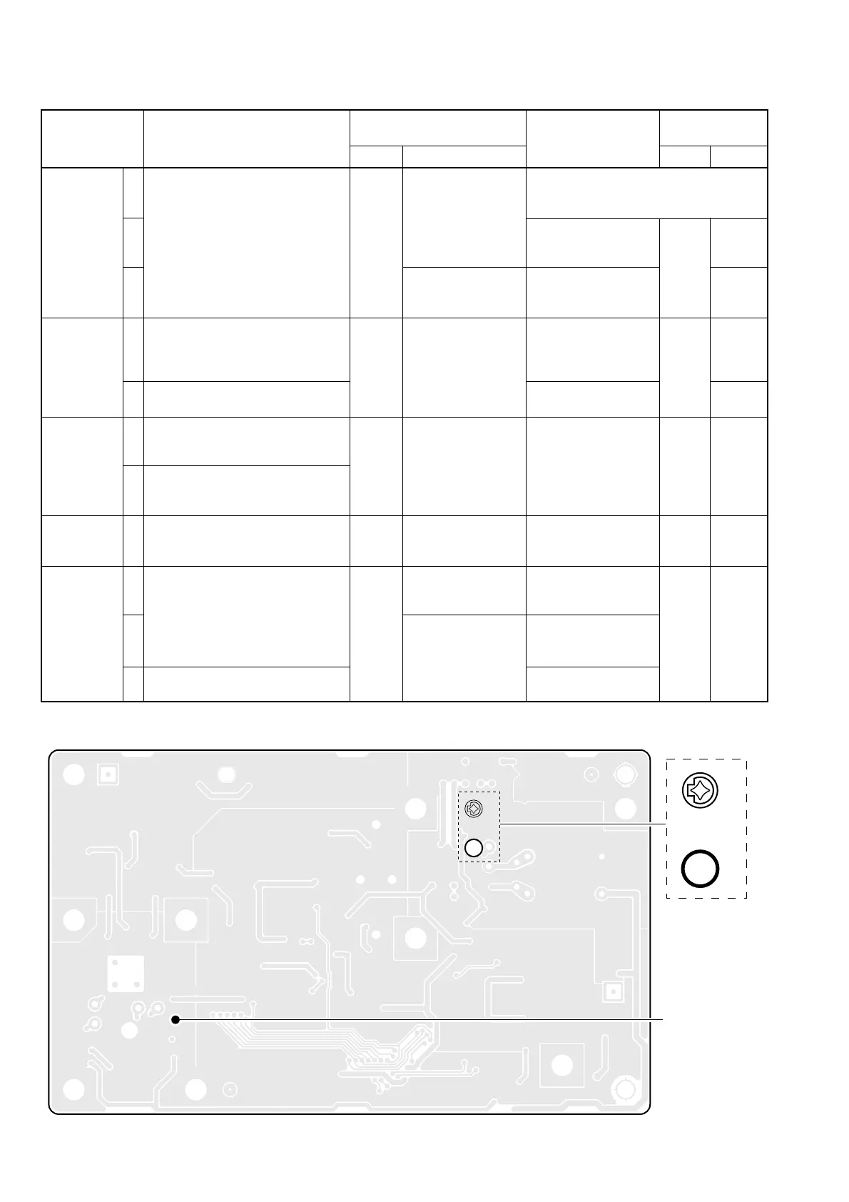
• Display frequency: Any
• Set C16 as illustration at below.
• Receiving
• Display frequency: 29.99999 MHz
• Receiving
• Display frequency: 0.03000 MHz
• Receiving
• Display frequency: 29.99999 MHz
• Mode : USB
• Receiving
• Display frequency: 0.03000 MHz
• Mode : LSB
• Receiving
• Display frequency: 14.10000 MHz
• Mode : USB
• Receiving
• Display frequency: 14.10000 MHz
• Mode : USB
• Receiving
• Mode : AM
• Receiving
PLL
PLL
PLL
PLL
PLL
Connect a frequency
counter to check
point P1.
Connect an RF volt-
meter to check point
P1.
Connect a digital
multimeter or oscillo-
scope to check point
CP1.
Connect an RF volt-
meter to check point
P4.
Connect an RF volt-
meter to check point
P1.
Connect an RF volt-
meter to check point
P5.
Connect a frequency
counter to check
point P5.
64.00000 MHz
Maximum level
4.15 V
More than 0.8 V
–3 dBm to +3dBm
–2 dBm to +4 dBm
–18 dBm to –12 dBm
456.5 kHz
No output
PLL
PLL
L4
L6, L7
C165
Verify
Verify
Verify
Verify
Turn L6, L7 on the PLL unit to downside for
presetting until the frequency counter reads
frequency.

 Loading...


