EasyManuals Logo

Icom IC-718 Service Manual Addendum

Icom IC-718
206 pages
To Next Page IconTo Next Page
To Previous Page IconTo Previous Page
Page #4 background imageLoading...
Page #4 background image
(Replacement page)
January 2013
7 - 3
*: Refer to BOARD LAYOUTS for the location.
**: Refer to GENERAL WIRING for the connection
Screw abbreviations A, B0, BT: Self-tapping PH: Pan head ZK: Black NI-ZU: Nickel-Zinc SUS: Stainless
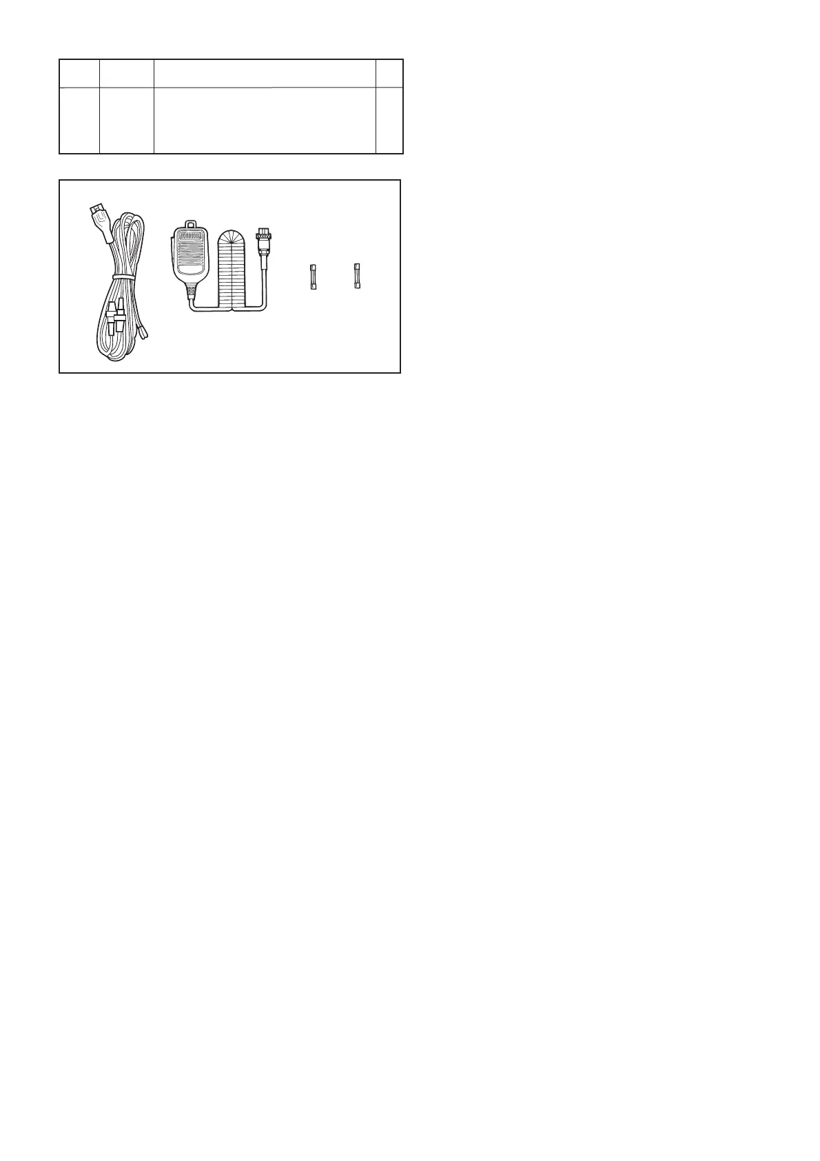
[ACCESSORIES]
REF ORDER
DESCRIPTION
QTY.
NO. NO.
F1 5210000080 FGB 20A 1
F2 5210000131 FGB 4A PBF 1
MC1 (Optional) HM-36 1
W1 8900000220 OPC-025 A 1
F1
W1 MC1
F2

Table of Contents

Other manuals for Icom IC-718

Questions and Answers:

Question and Answer IconNeed help?

Do you have a question about the Icom IC-718 and is the answer not in the manual?

Icom IC-718 Specifications

General IconGeneral
Input voltage13.8 V
Output power100 W
Frequency range0.5 - 1.799999 MHz
Channels quantity101 channels
Compatible productsAH-2B; AH-4; AH-710; AT-180; CT-17; FL-222; FL-257; FL-52A; FL-53A; HM-103; LC-156; MB-120; MB-62; MB-63; MB-72; OPC-581; OPC-587; OPC-589; OPC-599; PS-125; SM-20; SM-30; SP-10; SP-41; UT-102;
Display typeLCD
ManualYes
Product typePortable CB radio
Product colorBlack
Housing materialSteel
Weight and Dimensions IconWeight and Dimensions
Depth239 mm
Width240 mm
Height95 mm

Related product manuals