13
BASIC MANUAL
RECEIVING AND TRANSMITTING
4
1
2
3
4
5
6
7
8
9
10
11
12
13
14
15
16
17
18
19
20
21
Selecting the IF lter
The lter selection adjusts the IF bandpass width, as
shown to the right.
L Each operating mode memorizes the IF lter setting.
1. Select the desired mode with the mode keys.
2. Push [FIL] several times to select the desired filter
combination.
•
W
or
N
is not displayed when using the Normal
(standard) IF lter.
•
W
is displayed when the Wide IF lter is selected.
•
N
is displayed when the Narrow IF lter is selected.
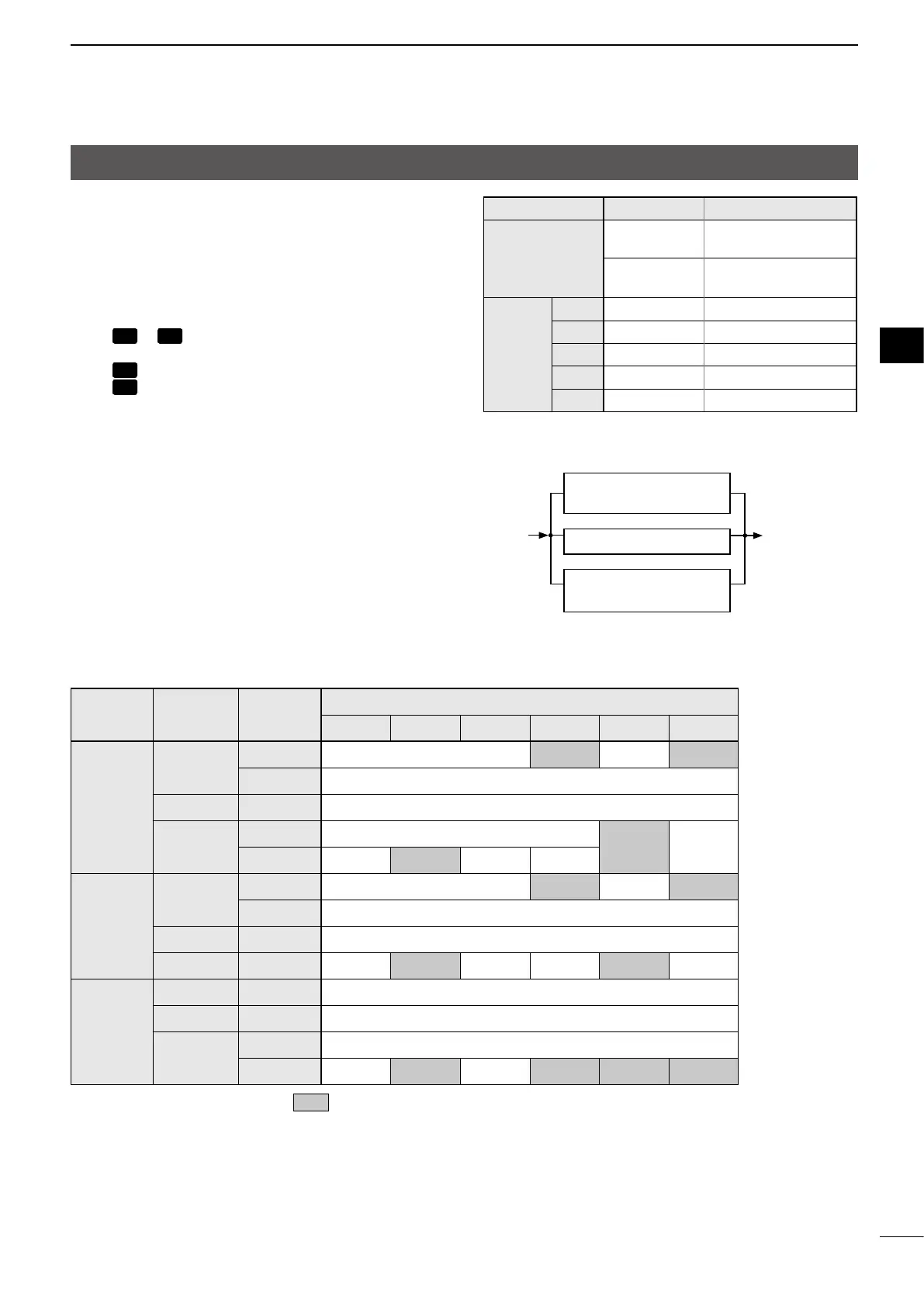
Filter selection table (Unit: Hz)
Mode
Filter
width
Expanded
lter
Optional lter
None 52A 53A 96 222 257
SSB
WIDE
OFF – 2.8 k – 3.3 k
ON 6 k
NORMAL OFF/ON 2.4 k
NARROW
OFF –
1.8 k –
ON – 500 250 –
CW
RTTY
WIDE
OFF – 2.8 k – 3.3 k
ON 6 k
NORMAL OFF/ON 2.4 k
NARROW OFF/ON – 500 250 – 1.8 k –
AM
WIDE OFF/ON –
NORMAL OFF/ON 6 k
NARROW
OFF 2.4 k
ON 2.4 k 500 250 2.8 k 1.8 k 3.3 k
L To use the lters marked with , you must set the short-pin on the main board.
Refer to the next page and set the short-pin to the position according to your desired lter width.
Filter Band width Mode
Standard
6 kHz
SSB/CW/RTTY: Wide
AM: Normal
2.4 kHz
SSB/CW/RTTY: Normal
AM: Narrow
Optional
52A 500 Hz/–6dB CW/RTTY: Narrow
53A 250 Hz/–6dB CW/RTTY: Narrow
96 2.8 kHz/–6dB SSB: Wide
222 1.8 kHz/–6dB SSB: Narrow
257 3.3 kHz/–6dB SSB: Wide
Filter image
Standard lter (6 kHz)
(Through)
Standard lter (2.4 kHz)
Optional lter
(Either one is selectable)
2nd IF
signal
2nd IF
signal/DET

 Loading...


