24
BASIC MANUAL
9
MAINTENANCE
D Troubleshooting
The following chart is designed to help you correct problems which are not equipment malfunctions.
If you are not able to locate the cause of a problem or solve it through the use of this chart, contact your nearest
Icom Dealer or Service Center.
Problem Possible cause Solution Ref.
POWER
Power does not turn
ON when [PWR] is
pushed.
• DC power cable is improperly connected.
• Fuse is blown.
• The external power supply is turned OFF.
• Properly reconnect the DC power cable.
• Turn ON the external power supply.
• Find and repair the cause of the problem, and then
replace the blown fuse with a new one.
p. 6
p. 6
p. 6
RECEIVE
No sound is heard
from the speaker.
• The audio level is too low.
• The squelch is closed.
• The transceiver is in the transmitting
mode.
• Rotate [AF] control clockwise to obtain a suitable
listening level.
• Rotate [RF/SQL] to around the 10 o'clock position to
open the squelch, and adjust the squelch level.
• Turn o the transmit mode.
p. 7
p. 10
–
Sensitivity is too low,
and only strong signals
are heard.
• The Antenna is not properly connected.
• The antenna for another band is
connected.
• The antenna is not properly tuned.
• The attenuator is activated.
• Reconnect the antenna connector.
• Connect an antenna suitable for the operating band.
• Hold down [TUNER] for 2 seconds to manually tune
the antenna.
• Turn OFF the Attenuator.
p. 5
p. 3
p. 11
Receive audio is
distorted.
• The operating mode is not selected
correctly.
• The IF SHIFT function is activated.
• The Noise blanker function is activated.
• The preamp is activated.
• For the USA version, Noise Reduction
function is activated and set too high.
• Select the correct operating mode.
• Rotate [SHIFT] to the center position.
• Push [NB] to turn OFF the function.
• Push [P.AMP] to turn OFF the function.
• Set the [NR] control for maximum readability.
p. 8
p. 12
p. 11
p. 11
p. 15
TRANSMIT
Cannot transmit. • The operating frequency is outside the
selected ham band.
• Set the frequency within the selected ham band. p. 9
Output power is too
low.
• RF power is too low.
• The microphone gain is too low.
• The selected antenna is for a dierent band.
• The antenna is not properly tuned.
• Set [RF POWER] to a suitable level.
• Set [MIC GAIN] to a suitable level.
• Select an antenna suitable for the operating frequency.
• Hold down [TUNER].
p. 10
p. 10
–
p. 1
Cannot contact with
another station.
• The RIT function is activated.
• The Split frequency function is activated.
• Push [RIT] to turn OFF the function.
• Push [SPLIT] to turn OFF the function.
p. 11
p. 15
Transmitted signal is
distorted.
• The microphone gain is too high.
• The microphone compressor function is
activated.
• Set [MIC GAIN] to a suitable level.
• Push [COMP] to turn OFF the Microphone
compressor function.
p. 10
p. 16
SCAN
Programmed scan
does not stop.
• Squelch is open.
• [RF/SQL] is assigned to RF gain control
and squelch is open.
• Set [RF/SQL] to the threshold point.
• Reset [RF/SQL] control assigned and set it to the
threshold point.
p. 10
p. 10
Programmed scan
does not start.
• The same frequencies have been entered
in scan edge memory channels P1 and
P2.
• Enter dierent frequencies in Scan Edge memory
channels P1 and P2.
p. 17
Memory scan does not
start.
• 2 or more memory channels have not
been entered.
• Enter 2 or more memory channels. p. 17
DISPLAY
The displayed
frequency does not
change when rotating
the main dial.
• The dial lock function is activated.
• A Quick Set mode screen is selected.
• The internal CPU has malfunctioned.
• Push [LOCK] to deactivate the function.
• Push [SET] to exit the Quick Set mode.
• Reset the CPU.
p. 9
p. 18
p. 7
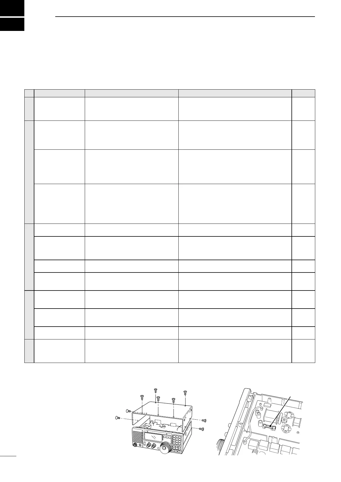
D Replacing the circuitry fuse
The 13.8 V DC from the DC power source is applied to all units in the IC-718 through the circuitry fuse.
The fuse is in the MAIN unit.
1. Remove the top cover of the
transceiver. (1)
2. Replace the circuitry fuse to a
brand-new one. (2)
3. Replace the top cover.
1
2
Circuitry fuse
(FGB 4A)
 Loading...


