5
BASIC MANUAL
3
4
5
6
7
8
9
10
11
12
13
14
15
16
17
18
19
20
21
2
1
2
INSTALLATION AND CONNECTIONS
Selecting a location
Select a location for the transceiver that allows
adequate air circulation, free from extreme heat, cold,
or vibration, and other electromagnetic sources.
Never place the transceiver in areas such as:
• Out of the specied temperature range (–10°C ~
+60°C, +14°F ~ +140°F).
• An unstable place that slopes or vibrates.
• In direct sunlight.
• High humidity and temperature environments.
• Dusty environments.
• Noisy environments.
Using the desktop stand
The transceiver has a stand for desktop use.
NOTE: DO NOT hold the stand, dials, or controls
when you carry the transceiver. This may damage
them.
Grounding
To prevent electrical shock, television interference
(TVI), broadcast interference (BCI) and other
problems, ground the transceiver through the
GROUND terminal [GND] on the rear panel.
For best results, connect a heavy gauge wire or strap
to a long ground rod. Make the distance between the
[GND] terminal and ground as short as possible.
R WARNING! NEVER connect the [GND] terminal
to a gas or electric pipe, since the connection could
cause an explosion or electric shock.
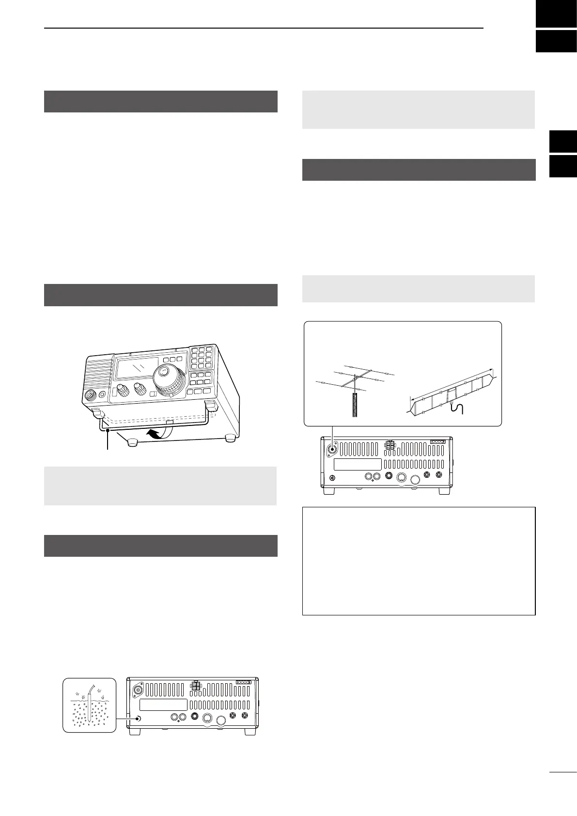
Connecting an antenna
For radio communications, the antenna is of critical
importance, along with output power and receiver
sensitivity.
Select antenna(s), such as a well-matched 50 Ω
antenna, and feedline. A Voltage Standing Wave Ratio
(VSWR) of 1.5:1 or less is recommended for your
desired band.
NOTE: A lightening arrestor may oer some
protection from static electricity.
Antenna
Example: For 1.8 to
30 MHz bands
AH-710
Approximately
24.5 m, 80.3 ft
Antenna SWR
Each antenna is tuned for a specied frequency
range and SWR may increase out of that range.
When the SWR is higher than approximately 2.0:1,
the transceiver’s power drops to protect the nal
transistor.
In this case, an antenna tuner is helpful to match the
transceiver and antenna. The IC-718 has an SWR
meter to continuously monitor the antenna SWR.