4 - 22
4-8 SCOPE UNIT ADJUSTMENTS
S3 LO LOCK
VOLTAGE
SCOPE
SCOPE GAIN
SCOPE
ATTENUATOR
ADJUSTMENT
ADJUSTMENT ADJUSTMENT CONDITION
MEASUREMENT
VALUE
POINT
UNIT LOCATION UNIT ADJUST
1
1
2
3
1
1
Pre-set the IC-7800 as the following
condition.
• MAIN display frequency
: 14.200 MHz
• Mode : CW
• Dualwatch : OFF
• Pre-amp. : OFF
• Attenuator : OFF
• Scope : ON
• Scope attenuator: OFF
• Span : ±25 kHz
• Receiving
• Connect an SSG to [ANT1] connec-
tor and set as;
Frequency : 14.200 MHz
Level :
500 µV* (–53 dBm)
Modulation: OFF
• Receiving
• Connect an SSG to J1 and set as;
Frequency : 71.715 MHz
Level : 100 mV* (–7 dBm)
Modulation: OFF
• Receiving
• Connect an SSG to [ANT1] connec-
tor and set as;
Frequency : 14.200 MHz
Level : 500 µV* (–53 dBm)
Modulation: OFF
• Receiving
• MAIN display frequency
: 14.200 MHz
• Mode : CW
• Connect an SSG to [ANT1] connec-
tor and set as;
Frequency : 14.200 MHz
Level : 500 µV* (–53 dBm)
Modulation: OFF
• Receiving
• MAIN display frequency
: 14.200 MHz
• Mode : CW
• Scope attenuator: 30 dB
• Connect an SSG to [ANT1] connec-
tor and set as;
Frequency : 14.200 MHz
Level : 500 µV* (–53 dBm)
Modulation: OFF
• Receiving
SCOPE
Front
panel
Front
panel
Front
panel
Connect a digital volt-
meter to CP801.
Scope wave on the
LCD.
Scope wave on the
LCD.
Scope wave on the
LCD.
2.5 V
Maximum wave form
Minimum wave form
Maximum wave form
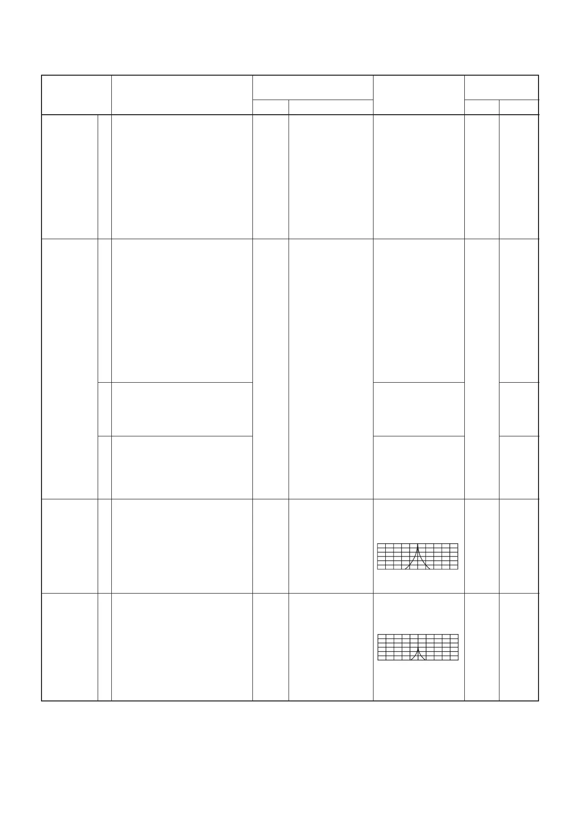
Set peak of scope
wave form to 6 scales
in the scope screen
Set peak of scope
wave form to 3 scales
in the scope screen.
SCOPE
SCOPE
SCOPE
SCOPE
C824
Adjust in
sequence
L203,
L202,
L201,
L5,
L6,
C41,
and
repeatedly
adjust L5,
L6 and
C41 in
sequence.
C41
Adjust
L5,
L6,
repeatedly.
R416
R11
*This output level of a standard signal generator (SSG) is indicated as SSG’s open circuit.

 Loading...


