SECTION 4 ADJUSTMENT PROCEDURE
4-1
4-1 PREPAR ATION
■ REQUIRED EQUIPMENT
EQUIPMENT GRADE AND RANGE EQUIPMENT GRADE AND RANGE
Programming
software
CS-M220 PROGRAMMING
SOFTWARE (Revision 1.00 or later)
JIG cable
Modied OPC-2132
(See the illustration shown on page 4-2.)
Programming
cable
OPC-478UC
Standard signal
generator (SSG)
★
With the pseudo
random code sending
function or the pulse
duty setting function.
Frequency range: 0.1~300 MHz
Output level: –20 dBµ to 90 dBµ
(–127 to –17 dBm)
RF power meter
(50 Ω terminated)
Measuring range: 0.1 ~ 30 W
Frequency range: 100 ~ 300 MHz
SWR: Less than 1.2 : 1
AC millivoltmeter Measuring range: 10 mV to 10 V
Modulation
analyzer
Frequency range: 30 ~ 300 MHz
Measuring range: 0 to ±10 kHz
Frequency counter
Frequency range: 0.1 ~ 300 MHz
Frequency accuracy: ±1 ppm or better
Oscilloscope
Frequency range: DC ~ 20 MHz
Measuring range: 0.01 ~ 20 V
Attenuator
Power attenuation: 40 dB
Capacity: More than 30 W
Audio generator
(AG)
Frequency range: 300 ~ 3000 Hz
Output level: 1 ~ 500 mV
External speaker
Input impedance: 4 Ω
Capacity: More than 10 W
Spectrum analyzer Measuring range: Up to 3 GHz
Distortion meter
Measuring accuracy: 3% or less at 1 kHz
Input level: 50 mV to 20 V
Bit error meter Input level: 0.1 ~ 2.0 Vp-p
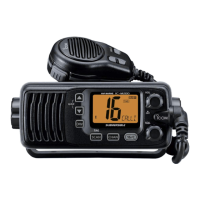
■ CONNECTION
CLOCK
CLOCK
BIT ERROR METER
(0.1 ~ 2.0 Vp-p)
+ −
DATA
Blue: SP+
White: NMEAO+
Brown: NMEAO−
Black: SP−
DISTORTION METER
(3% or less at 1 kHz/50 mV ~ 10 V)
Transceiver
Transceiver
DC power supply
13.8 V/10 A
–
+
CAUTION!
NEVER transmit while the SSG is
connected to the antenna connector.
Loose couple
JIG cable
Modulation analyzer
30 ~ 300 MHz/0 to ±10 kHz
Spectrum analyzer
Up to 3 GHz
Attenuator
40 dB
RF power meter
0.1 ~ 30 W/50 Ω
Frequency
counter
Standard signal generator
–20 to 90 dBµ
(–127 to –17 dBm)
OPC- 478UC
PC
to USB port
AF out leadsNMEA out leads
+ −
EXTERNAL SPEAKER
(10 W/4 Ω)
+
−