46
13
HM-127 REMOTE-CONTROL MICROPHONE
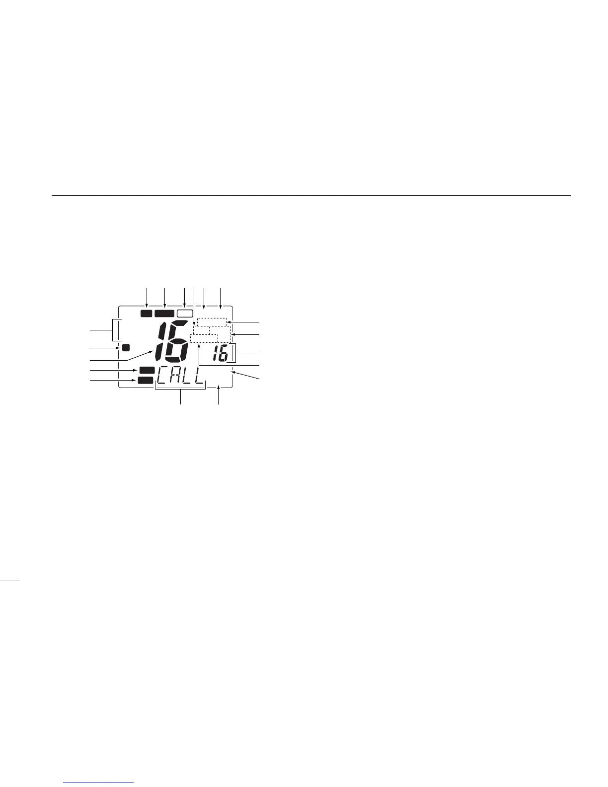
■ Function display
q CHANNEL GROUP INDICATOR (pgs. 6, 50)
Indicates whether an International (INT), U.S.A. (USA) or
Canadian (CAN) channel is selected.
w KEY LOCK INDICATOR (p. 52)
➥Appears while the key lock function is in use.
➥ Flashes while the all key lock function is in use.
e CHANNEL NUMBER READOUT
➥Indicates the selected operating channel number. “A”
appears when a simplex channel is selected. (pgs. 6,
50)
➥In set mode, indicates the selected condition. (pgs. 30,
55)
r VOLUME INDICATOR (p. 51)
Appears while audio output level is adjusted.
t SQUELCH INDICATOR (p. 51)
Appears while noise squelch level is adjusted.
y CHANNEL NAME INDICATOR
➥Channel comment appears (and scrolls) if programmed.
(pgs. 9, 56)
➥In set mode, indicates or scrolls the selected set mode
item. (pgs. 30, 55)
u ATTENUATOR INDICATOR (pgs. 8, 51)
Appears when the RF attenuator is in use.
i SCRAMBLER INDICATOR (pgs. 10, 53)
Appears when an optional voice scrambler is activated.
o SCAN INDICATOR (pgs. 13, 54)
➥“SCAN” appears during normal scan.
➥ “P SCAN” appears during priority scan.
!0 PRIORITY CHANNEL INDICATOR
➥Indicates a priority channel during priority scan or
dual/tri-watch. (pgs. 12, 54)
➥ “IC” appears during intercom mode. (pgs. 29, 56)