58
CONNECTIONS AND MAINTENANCE
9
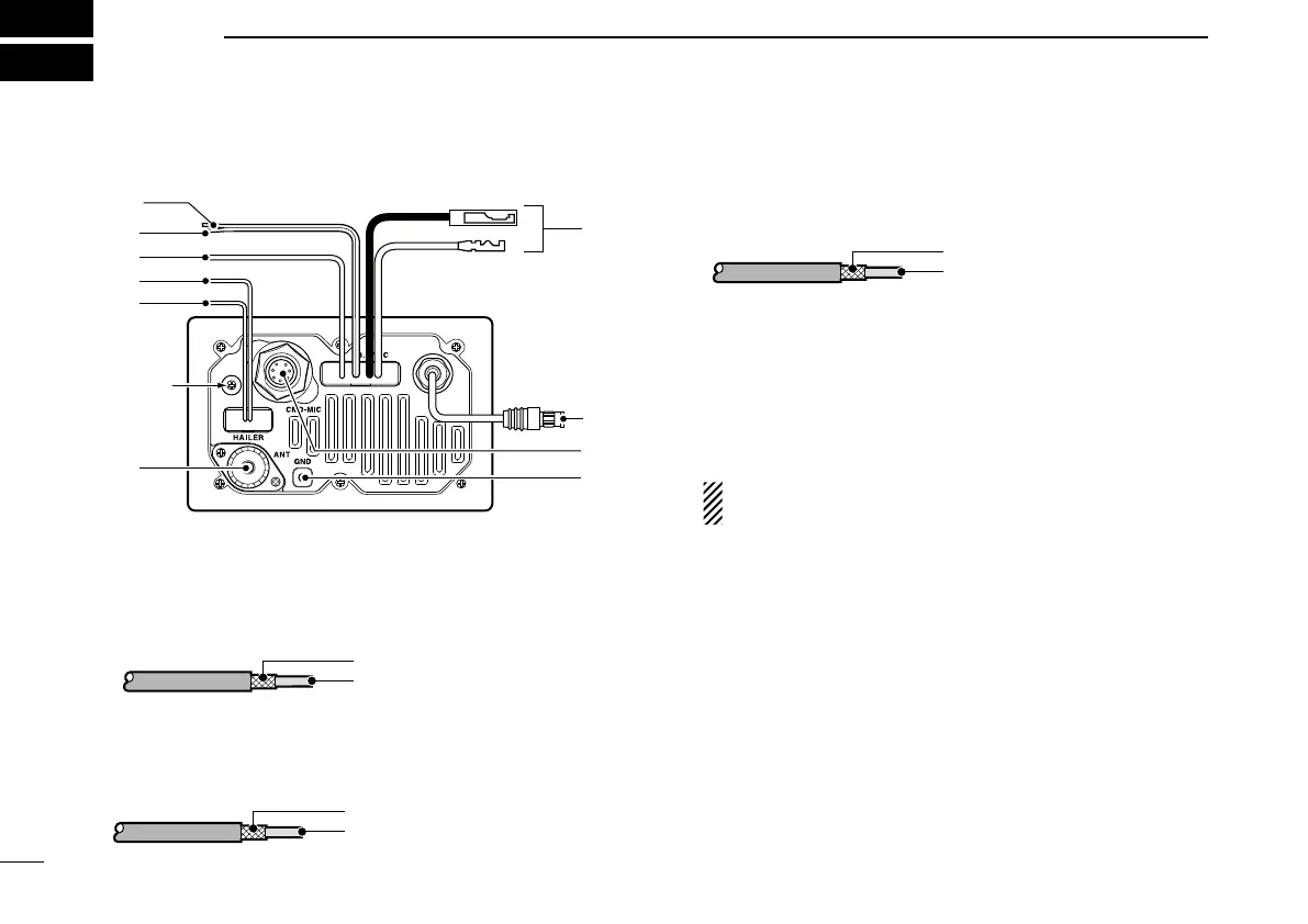
■ Connections
q NMEA IN LEAD (Red)
Connects to a GPS receiver for position indication.
•ANMEA0183ver.2.0or3.01(sentenceformattersRMC,GGA,
GNS, GLL and VTG) compatible GPS receiver is required. Ask
your dealer about suitable GPS receivers.
w NMEA OUT LEAD (White)
Connects to a PC or navigation equipment (NMEA0183
ver. 3.01 sentence formatters DSC, DSE compatible) for
position data received from other ships.
e EXTERNAL SPEAKER LEAD (Yellow)
Connects to an external speaker.
r HAILER/FOGHORN (–) LEAD (Black)
Connects to a hailer speaker (25 W nominal at 13.8 V/4 ˘).
t HAILER/FOGHORN (+) LEAD (Blue)
Connects to a hailer speaker (25 W nominal at 13.8 V/4 ˘).
y ANTENNA CONNECTOR
Connects a marine VHF antenna with a PL-259 connec-
tor to the transceiver.
CAUTION: Transmitting without an antenna may dam-
age the transceiver.
u GROUND TERMINAL
Connect this terminal to a vessel ground to prevent elec-
trical shocks and interference from other equipment oc-
curring. Use a self-tapping screw (3 × 8 mm.)
i EXTERNAL MICROPHONE JACK
Connects the optional command microphone.
o MICROPHONE CONNECTOR
Connects the supplied microphone depending on version.
Ask your dealer for details.
!0 DC POWER CONNECTOR
Connects the supplied DC power cable from this connec-
tor to an external 12 V battery.
Inner conductor
Outer conductor
: NMEA OUT (+)
: NMEA OUT (−)
Inner conductor
Outer conductor
: NMEA IN (+)
: NMEA IN (−)
Inner conductor
Outer conductor
: Speaker (+)
: Speaker (−)

 Loading...


