4 - 4
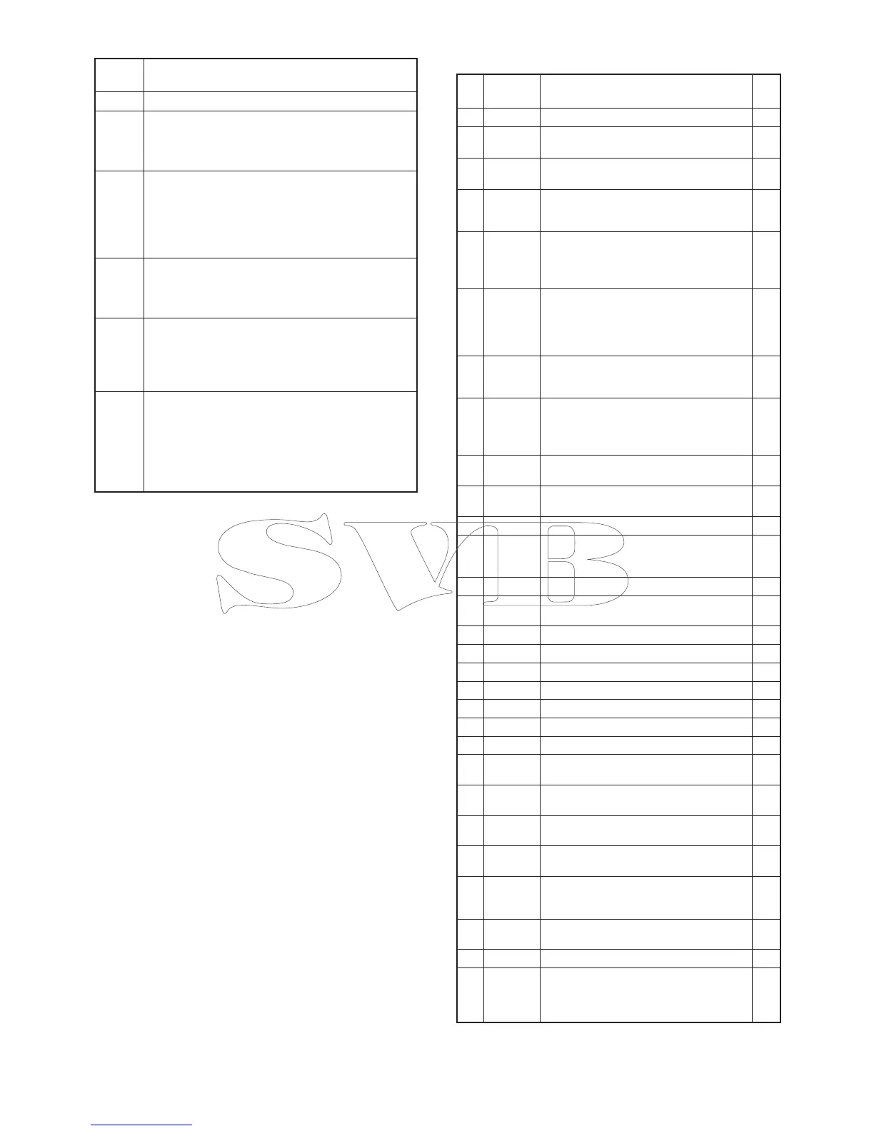
4-4 POWER SUPPLY CIRCUITS
Line
name
Description
VCC The same voltage as attached battery pack.
CPU5V
Common 5 V converted from VCC line by the
CPU5V regulator (IC220).
The voltage is applied to the CPU (IC360), Reset
IC (IC341), EEPROM (IC340), etc.
5V
Common 5 V converted from VCC line by the 5V
regulator (Q223−Q225) controlled by "M5VS" sig-
nal from the CPU (IC360, pin 101).
The voltage is applied to the backlight LED'S
(DS240−DS243, DS250−DS253), D/A converter
(RF UNIT: IC190), PLL IC (RF UNIT: IC1), etc.
V5V
Common 5 V converted from VCC line by the V5V
regulator (RF UNIT: Q220).
The voltage is applied to the VCO (RF UNIT:
Q21, Q22, D20−D22)
R5V
Receive 5 V controlled by the R5V regulator (Q221)
using "R5VS" signal from the CPU (IC360, pin 95).
The voltage is applied to the receive circuits (RF
UNIT: 1st mixer (Q150), 1st IF amplifier (Q151),
RF amplifi er (Q90), etc.).
T5V
Transmit 5 V controlled by the T5V regulator (RF
UNIT: Q222) using "T5VS" signal from the CPU
(IC360, pin 13).
The controlled voltage is applied to the transmit
circuits (RF UNIT: differential amplifi er (IC50), pre-
driver (Q53), power amplifier (Q54), microphone
amplifi er (IC8), etc.).
Pin
No.
Port
Name
Description I/O
1 BEEP Beep sound to the AF circuits. O
4
DAST
(DAST)
Strobe signal to the D/A converter (IC190,
pin 3).
O
5
PLSTB
(PLST)
PLL strobe signal to the PLL IC (RF UNIT:
IC1, pin 8).
O
11
SCLK
(SCK)
Serial clock signal to the PLL IC (RF UNIT:
IC1, pin 6) and D/A converter (IC190,
pin 4).
O
12 V5VS
V5V regulator (Q220) control signal.
"High"= While in the power save mode (The
VCO
(Q21, Q22, D21−D23) is
not activated).
O
13 T5VS
T5V regulator (RF UNIT: Q222) control
signal.
"Low"= While transmitting.
"High"= While receiving or in the power
save mode.
O
14 LCDS
LCD contrast select signal.
"Low"= While "Bright" is selected.
"High"= While "Dark" is selected.
O
15 LEDS
Backlight LED (DS240
−
DS243,
DS250
−
DS253) control signal to the LED
driver (Q240).
"High"= While the backlight is ON.
O
25 RES
Reset signal from the reset IC (IC341,
pin 4).
I
27
†
WDECV
Demodulated weather alart (WX) signal
from the AF circuit.
I
28 EXDET External connection detect. I
29 VOXT
Voice input detection from the VOX
amplifier (IC431, pin 7) for the VOX
operation.
I
30 BATTV Remaining battery voltage. I
31 TDETV
TX power level sensing voltage from the
transmit power detector (RF UNIT: D91).
I
32 NOISV Noise level from the IF IC (IC170, pin 14). I
33 RSSIV RSSI signal from the IF IC (IC170, pin 12). I
34 LOINV Lock voltage. I
35 TEMPV Temperture sensing voltage. I
36 WET Water leaking detection. I
93 ESCK Serial clock to the EEPROM (IC501, pin 6). O
94 ESDA Serial data to the EEPROM (IC501, pin 5). O
95 R5VS
R5V line regulator (Q221) control.
"High"= While receiving.
O
96 EXPTT
External PTT.
"High"= The external PTT is pushed.
I
97 TXMS
Transmit mute switch (Q351) control.
"Low"= While receiving. (Mute)
O
98 DETMS
AF mute switch (IC430, pin 12) control.
"High"= While the squelch is open.
O
100 AFVS
AF power amplifier power supply switch
control.
"High"= While the amplifi er is activated.
O
102 PTTIN
Input port for [PTT]. (RF UNIT: S250)
"High": Pushed.
I
104 BTYPE Battery type detection. I
105 PTTM
AF mute switch (IC430, pin 13) control.
"High": While transmitting.
"Low": While transmitting with VOX
function.
O
4-5 PORT ALLOCATIONS
• CPU (MAIN UNIT: IC360)