4-2
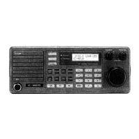
• TRANSCEIVER FRONT PANEL (2)
EXT-SP
CONTROLLER
ACC MAINTENANCE
[GPS-DATA]
[REMOTE]
[AF/MOD]
[AF/MOD]
AF/MOD
Pin
number
Pin
name
Description Specification
9-pin
5 1
69
Front panel view
1 MOD+
Modulation input from an external terminal
unit.
Input impedance: More than 600 Ω
Input level: Approximately
0.77 V rms
2 MOD− Ground terminal for MOD+. –
3 GND Ground terminal for transceiver. –
4 AF+
Detected audio output for an external
terminal unit.
Output impedance
: More than 600 Ω
Output level: Approximately
770 mV rms
5 AF− Ground terminal for AF+. –
6 GND Ground terminal for transceiver. –
7 NC This pin is not connected anywhere. –
8 SEND Transmits when grounded.
Ground level: −0.5~+0.8 V
Input current: Less than 20 mA
9 GND Ground terminal for transceiver. –
[REMOTE]
REMOTE
Pin
number
Pin name Description
9-pin
5 1
69
Front panel view
1 DCD Carrier detection input.
2
RXD Receive data input.
NMEA-OUT NMEA0183 ver 4.10 data output.
3
TXD Transmit data output.
NMEA-IN NMEA0183 ver 4.10 data input.
4 DTR Terminal ready signal output.
5 GND Ground terminal for transceiver.
6 DSR Data-set-ready signal input.
7 RTS Request-to-send data output.
8 CTS Clear-to-send data input.
9 NC No connection.
[GPS-DATA]
GPS-DATA
Pin
number
Pin name Description
1
BNC
2
Front panel view
1
NMEA
NMEA0183 ver 4.10 data input.
2
NMEA
Ground for NMEA .
 Loading...