4-1
SECTION 4 INTERFACE INFORMATION
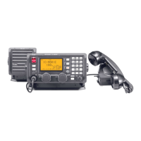
• REMOTE CONTROLLER
[MIC]
[MIC]
MIC
Pin
number
Pin
name
Description Specification
8-pin
1
2
3
4
5
6
7
8
Front panel view
1 MIC+ Audio input from the microphone element. Input impedance: 1.74 kΩ ±20%
2 NC No connection. –
3 AF1
Audio output related to the volume setting.
Connected to pin 4 in the microphone.
–
4 AF2
Audio input.
Connected to pin 3 in the microphone.
–
5 PTT PTT switch input. When grounded, transmits.
6 GND Ground terminal for transceiver. –
7 MIC‒ Ground terminal for MIC+. –
8 AF‒ Ground terminal for AF1 and AF2. –
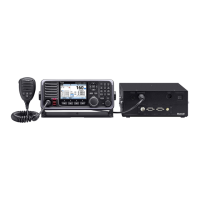
• TRANSCEIVER FRONT PANEL (1)
[ACC]
EXT-SP
CONTROLLER
ACC MAINTENANCE
[ACC]
ACC
Pin
number
Pin
name
Description Specification
8-pin
1
2
3
45
67
8
Front panel view
1 CWK CW and FSK keying input.
Input level: −0.5~+0.8 V
2 AF GND Ground terminal for AF. –
3 SEND
Input/Output terminal.
Transmits when grounded.
Ground level: −0.5~+0.8 V
Input current: Less than 20 mA
4 MOD
Modulator input.
- Usable when pin 3 is grounded.
Input impedance: More than 10 kΩ
Input level: Approximately
100 mV rms
5 AF
Audio detector output.
- Fixed, regardless of [VOL] position.
Output impedance:
Less than 4.7 kΩ
Output level: 100~300 mV rms
6 NC No connection. –
7 13.6 V 13.6 V output when power is ON.
Output current: Less than 1 A
8 ALC ALC voltage input.
Control voltage: −3~0 V
Input impedance: More than 10 kΩ
 Loading...