10
34
OPTION INSTALLATIONS
■ Opening the receiver’s case
Follow the case and cover opening procedures shown
here when you want to install an optional unit or
adjust an internal unit, etc.
CAUTION: DISCONNECT the DC power cable
from the receiver before performing any work on
the receiver. Otherwise, there is danger of electric
shock and/or equipment damage.
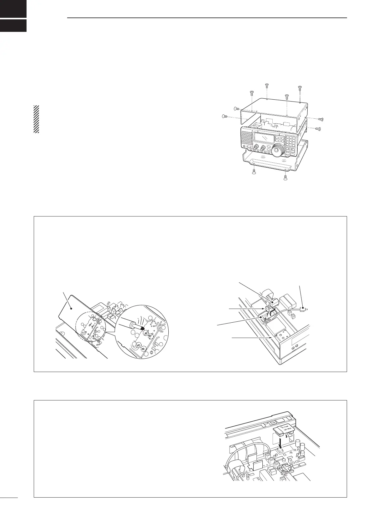
q Remove the 2 screws from the left side of the
receiver to remove an optional carrying handle, if
necessary.
w Remove the 4 screws from the top of the receiver
and 4 screws from the sides, then lift up the top
cover.
e Remove the 2 screws from the bottom of the
receiver, slide the cover backward, then remove
the bottom cover.
The UT-102 announces the received frequency, mode,
S-meter level and current time in a clear, electronically-
generated voice, in English (or Japanese).
➥ Pus h [ LO CK ] fo r 2 se c. t o ann ou nce the
frequency, etc.
q Remove the top cover as shown above.
w Remove the protective paper attached to the
bottom of the UT-102 to expose the adhesive strip.
e Plug UT-102 into J1271 on the MAIN unit as
shown at right.
r Return the top cover to its original position.
■ CR-282 high stability crystal unit
By installing the CR-282, the total frequency stability
of the receiver will be improved.
q Remove the top cover as shown in the diagram
above.
w Remove 5 screws from the PLL unit, disconnect
P1 from J491 (MAIN unit), then remove the PLL
unit.
e Remove the supplied internal crystal and replace
with the CR-282.
r Adjust the reference frequency at L2 using a
frequency counter.
t Return the PLL unit and top cover to their original
positions.
PLL unit
MAIN unit
CR-282
Internal
crystal
Connect a frequency counter
here and adjust the frequency
to 60.00000 MHz.
L2
■ UT-102 voice synthesizer unit

 Loading...


