8. AIRFLOW ADJUSTMENT
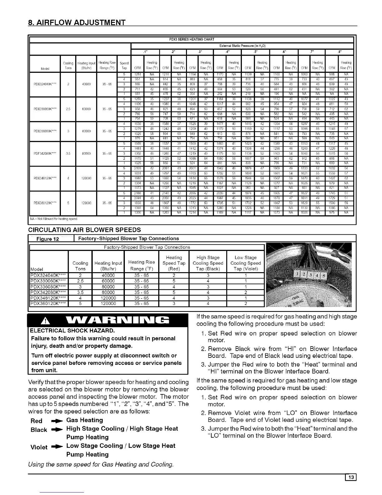
PDX3 SERIES HEATING CHART
External Static Pressure (in H2O )
1" .2" 3" 4" .5" 6" .T' .8"
Cooling Heatinglnpu_ Heating Rise Speed Heating Heating Heating Heating Heating Heating Heat}ng Heating
M0del Tons (BNih0 Range(_F) Tap OFM Rise(°F/ OFM Rise(°F) OFM Rise(°F/ OFM Rise(°F) OFM Rise(°F) CFM Rise(°F) CFM Rise(_F) CFM Rise(°F)
5 125/ NA /218 NA /I94 NA 1170 NA lt3g NA tt0O NA /063 NA 988 NA
4 951 NA 914 NA 883 NA 858 35 8II 37 775 38 733 40 697 43
PDX32404OK.... 2 40000 35 65 3 869 NA 842 35 809 37 768 39 736 40 684 43 650 46 599 49
2 7II 42 655 45 623 48 564 53 529 56 48/ 62 43/ NA 392 NA
I 661 45 4(8 62 334 NA 262 NA 219 NA /96 NA NA NA NA NA
5 1255 35 /227 36 /291 37 1164 38 1138 39 1II2 40 /077 4I /027 43
4 1106 40 I080 41 I048 42 1017 44 992 45 g54 47 924 48 88/ 50
PDX33O06OK.... 25 60000 35 65 3 958 46 923 48 894 50 857 52 828 54 786 57 750 59 712 62
2 789 56 747 5g 7/4 62 668 NA 630 NA 582 NA 542 NA 495 NA
I (b4 bg /08 63 6(I NA 618 NA b84 NA 524 NA 494 NA 443 NA
4 1630 36 /588 37 /526 39 1477 40 1415 42 /354 44 /287 46 /216 49
3 1276 46 /242 48 /209 49 1179 50 1150 52 1II7 53 /086 55 1045 57
PDX336080K.... 3 80000 35 65
2 1026 58 994 6g 949 62 9/3 65 87I NA 841 NA 793 NA 735 NA
1 8(6 NA 84I NA (94 NA (b6 NA 694 NA 65/ NA 598 NA 543 NA
5 1569 38 /537 39 150g 40 1463 41 1423 42 I389 43 /353 44 1317 45
4 1481 40 /448 41 /412 42 1374 43 1336 44 /298 46 /263 47 /226 48
PDF342080K.... 35 80000 35 65 3 1302 46 /260 47 /21g 49 1179 5g 1138 52 1103 54 /06g 56 /015 58
2 1170 51 II29 52 I088 54 1050 56 1007 59 g63 62 912 65 866 NA
1 1028 b6 969 61 924 64 88I NA 838 NA /89 NA /3I NA 660 NA
5 2103 42 2051 43 2001 44 1942 46 1878 47 I809 49 /723 52 1632 54
4 183I 49 1797 49 1763 50 1732 51 1696 52 /661 54 1621 55 /559 57
PDX348120K.... 4 120000 35 65 3 1680 53 /650 54 /614 55 1578 56 1544 58 1507 59 /470 60 /427 62
2 1304 NA I256 NA I216 NA 1167 NA 1126 NA /077 NA I026 NA 979 NA
1 11/3 NA 112/ NA 1065 NA I02/ NA 983 NA 92( NA 88I NA 82/ NA
5 2188 41 2140 42 2096 42 2039 44 1974 45 /905 47 /827 49 /745 51
4 209I 43 2056 43 2023 44 1987 45 1935 46 /878 47 1811 49 /729 5/
PDX360120K.... 5 120000 35 65 3 1839 48 /807 49 /772 50 1735 51 1702 52 1667 53 /629 55 /590 56
2 1393 64 I356 NA 1313 NA 1280 NA 1226 NA /I84 NA II30 NA I086 NA
1 1300 NA 1263 NA 1214 NA II69 NA 111/ NA /g/3 NA 1026 NA 9/b NA
NA No, Allowed_rheating speed
CIRCULATING AIR BLOWER SPEEDS
Fi,qure 12 Factory-Shipped Blower Tap Connections
Factory-Shipped Blower Tap Connections
Cooling Heating Input
_4odel Tons (Btu/hr)
_DX324040K .... 2 40000
_DX33006gK .... 2.5 60000
_DX336080K .... 3 80000
_DX34208gK .... 3.5 80000
_DX348120K .... 4 120000
_DX360120K .... 5 120000
Heating Rise
Range (°F)
35 - 65
35 - 65
35 - 65
35 - 65
35 - 65
35 - 65
Heating
Speed Tap
(Red)
2
5
4
5
4
3
High Stage
Cooling Speed
Tap (Black)
3
4
3
4
3
4
Low Stage
Cooling Speed
Tap (Violet)
I
I
I
2
1
2
ELECTRICAL SHOCK HAZARD.
Failure to follow this warning could result in personal
injury, death and/or property damage.
Turn off electric power supply at disconnect switch or
service panel before removing access or service panels
from unit.
Ifthe same speed is required for gas heating and high stage
cooling the following procedure must be used:
1. Set Red wire on proper speed selection on blower
motor.
2. Remove Black wire from "HI" on Blower Interface
Board. Tape end of Black lead using electrical tape.
3. Jumper the Red wire to both the "Heat" terminal and
"HI" terminal on the Blower Interface Board.
Verify that the proper blower speeds for heating and cooling Ifthe same speed is required for gas heating and low stage
are selected on the blower motor by removing the blower cooling, the following procedure must be used:
access panel and inspecting the blower motor. The motor 1. Set Red wire on proper speed selection on blower
has up to 5 speeds numbered "1 ", "2", "3", "4", and "5". The
wires for the speed selection are as follows:
Red _ Gas Heating
Black _ High Stage Cooling / High Stage Heat
Pump Heating
Violet miD" Low Stage Cooling / Low Stage Heat
Pump Heating
Using the same speed for Gas Heating and Cooling.
motor.
2. Remove Violet wire from "LO" on Blower Interface
Board. Tape end of Violet lead using electrical tape.
3. Jumper the Red wire to both the "Heat" terminal and the
"LO" terminal on the Blower Interface Board.
 Loading...