Condensate Drain
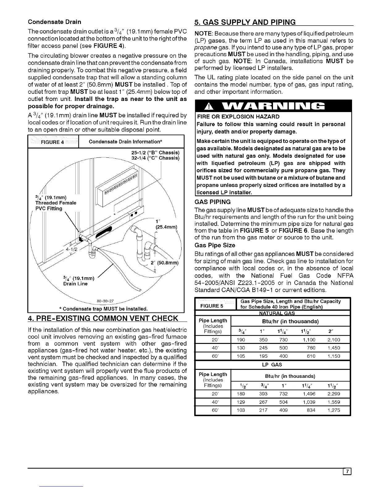
The condensate drain outlet is a 3/4" (19.1mm) female PVC
connection located atthe bottom ofthe unit to the right ofthe
filter access panel (see FIGURE 4).
The circulating blower creates a negative pressure on the
condensate drain line that can prevent the condensate from
draining properly. To combat this negative pressure, a field
supplied condensate trap that will allow a standing column
of water of at least 2" (50.8mm) MUST be installed. Top of
outlet from trap MUST be at least 1" (25.4mm) below top of
outlet from unit. Install the trap as near to the unit as
possible for proper drainage.
A 3/4" (19.1 mm) drain line MUST be installed if required by
local codes or if location of unit requires it. Run the drain line
to an open drain or other suitable disposal point.
FIGURE 4 Condensate Drain Information*
b
25-1/2 ("B" Chassis)
32-1/4 ("C" Chassis)
3/4" (19,1mm)
Threaded Female
PVC Fitting
1 "
(25.4mm)
/
2" (5O.8mm)
80-30-27
* Condensate trap MUST be installed,
4. PRE-EXISTING COMMON VENT CHECK
If the installation of this new combination gas heat/electric
cool unit involves removing an existing gas-fired furnace
from a common vent system with other gas-fired
appliances (gas-fired hot water heater, etc.), the existing
vent system must be checked and inspected by a qualified
technician. The qualified technician can determine if the
existing vent system will properly vent the flue products of
the remaining gas-fired appliances. In many cases, the
existing vent system may be oversized for the remaining
appliances.
5. GAS SUPPLY AND PIPING
NOTE: Because there are many types of liquified petroleum
(LP) gases, the term LP as used in this manual refers to
propane gas. If you intend to use any type of LP gas, proper
precautions MUST be used in the handling, piping, and use
of such gas. NOTE: In Canada, installations MUST be
performed by licensed LP installers.
The UL rating plate located on the side panel on the unit
contains the model number, type of gas, gas input rating,
and other important information.
FIRE OR EXPLOSION HAZARD
Failure to follow this warning could result in personal
injury, death and/or property damage.
Makecertainthe unit isequipped to operateonthe type of
gasavailable. Models designated as natural gas are to be
used with natural gas only. Models designated for use
with liquefied petroleum (LP) gas are shipped with
orifices sized for commercially pure propane gas. They
MUSTnot be usedwith butane or a mixture of butaneand
propane unless properly sized orifices are installed bya
licensed LP installer.
GAS PIPING
The gas supply line MUST be of adequate size to handle the
Btu/hr requirements and length of the run for the unit being
installed. Determine the minimum pipe size for natural gas
from the table in FIGURE 5 or FIGURE 6. Base the length
of the run from the gas meter or source to the unit.
Gas Pipe Size
Btu ratings of all other gas appliances MUST be considered
for sizing of main gas line. Check gas line to installation for
compliance with local codes or, in the absence of local
codes, with the National Fuel Gas Code NFPA
54-2005/ANSI Z223.1-2005 or in Canada the National
Standard CAN/CGA B149-1 or current editions.
FIGURE 5
Gas Pipe Size, Length and Btu/hr Capacity
for Schedule 40 Iron Pipe/English/
NATURAL GAS
Pipe Length Btu/hr (in thousands)
(includes
Fittings) 3/4" 1" 11/4" 11/2" 2"
20' 190 350 730 1,100 2,100
40' 130 245 500 760 1,450
60' 105 195 400 610 1,150
LP GAS
Pipe Length Btu/hr (in thousands)
(includes
Fittings) 1/2" 3/4" 1" 11/4"
20' 189 393 732 1,496
40' 129 267 504 1,039
60' 103 217 409 834
11/2"
2,299
1,559
1,275
171
 Loading...