3. LOCATING THE UNIT
ACCESS PANELS
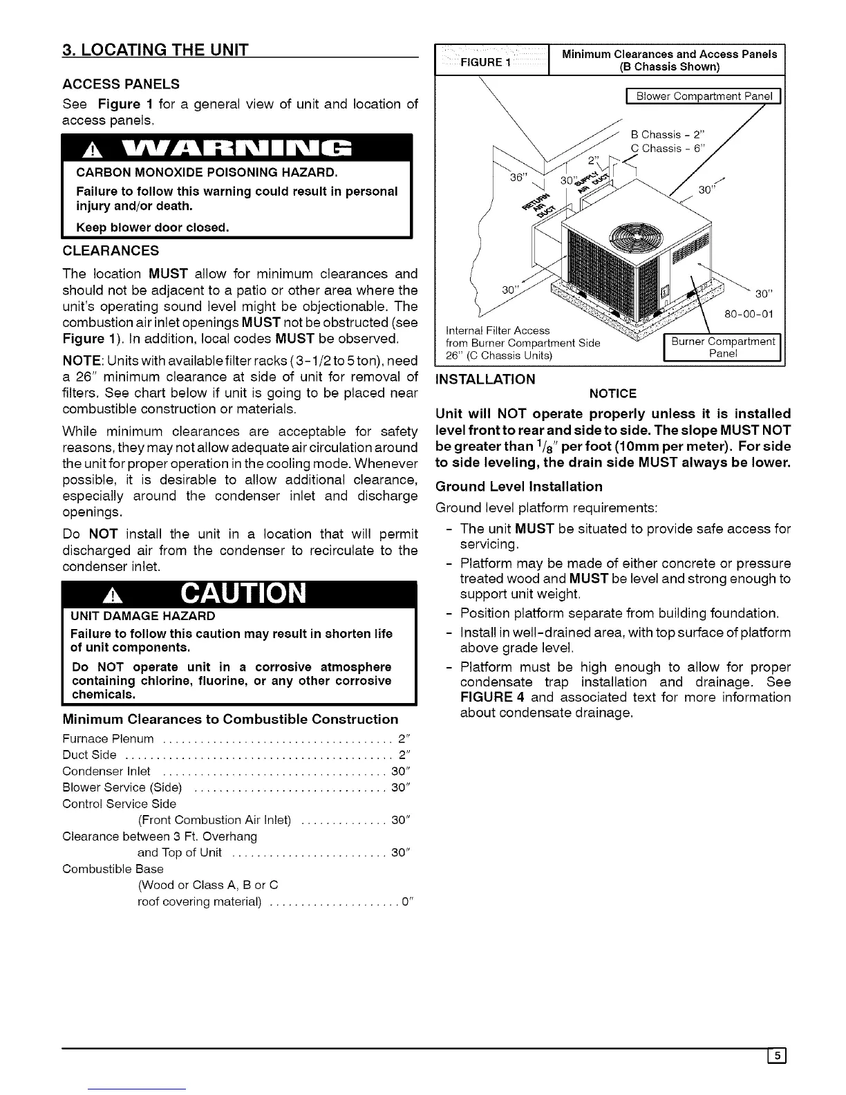
See Figure 1 for a general view of unit and location of
access panels.
CLEARANCES
The location MUST allow for minimum clearances and
should not be adjacent to a patio or other area where the
unit's operating sound level might be objectionable. The
combustion air inlet openings MUST not be obstructed (see
Figure 1). In addition, local codes MUST be observed.
NOTE: Units with available filter racks (3-1/2 to 5ton), need
a 26" minimum clearance at side of unit for removal of
filters. See chart below if unit is going to be placed near
combustible construction or materials.
While minimum clearances are acceptable for safety
reasons, they may not allow adequate air circulation around
the unit for proper operation inthe cooling mode. Whenever
possible, it is desirable to allow additional clearance,
especially around the condenser inlet and discharge
openings.
Do NOT install the unit in a location that will permit
discharged air from the condenser to recirculate to the
condenser inlet.
UNIT DAMAGE HAZARD
Failure to follow this caution may result in shorten life
of unit components.
Do NOT operate unit in a corrosive atmosphere
containing chlorine, fluorine, or any other corrosive
chemicals.
Minimum Clearances to Combustible Construction
Furnace Plenum ..................................... 2"
Duct Side ........................................... 2"
Condenser Inlet .................................... 30"
Blower Service (Side) ............................... 30"
Control Service Side
(Front Combustion Air Inlet) .............. 30"
Clearance between 3 Ft. Overhang
and Top of Unit ......................... 30"
Combustible Base
(Wood or Class A, B or C
roof covering material) ..................... 0"
FIGURE i Minimum Clearances and AccessPanels(BChassis Shown)
I Blower Compartment Panel
B Chassis - 2"
C Chassis - 6"
Internat Filter Access
from Burner Compartment Side
26" (C Chassis Units)
Burner Compartment
Panel
INSTALLATION
NOTICE
Unit will NOT operate properly unless it is installed
level front to rear and side to side. The slope MUST NOT
be greater than 1/8" per foot (10mm per meter). For side
to side leveling, the drain side MUST always be lower.
Ground Level Installation
Ground level platform requirements:
- The unit MUST be situated to provide safe access for
servicing.
- Platform may be made of either concrete or pressure
treated wood and MUST be level and strong enough to
support unit weight.
- Position platform separate from building foundation.
- Install in well-drained area, with top surface of platform
above grade level.
- Platform must be high enough to allow for proper
condensate trap installation and drainage. See
FIGURE 4 and associated text for more information
about condensate drainage.
151
 Loading...