Rooftop Installation
Rooftop platform requirements:
- The unit MUST be situated to provide safe access for
servicing.
- The existing roof structure MUST be adequate to
support the weight of the unit or the roof MUST be
reinforced.
Check the weight of the unit in relation to the roof
structure and local building codes or ordinances and
reinforce roof structure if necessary. See the last page
of this manual for unit weights.
- Support for the unit MUST be level and strong enough
to carry unit weight. The support may consist of a
platform or a combination of platform and roof beams or
curb.
- See Hoisting section for hoisting instructions,
HOISTING
NOTE: All access panels MUST be secured in place before
hoisting.
The unit should be hoisted with two lifting slings. Attach the
slings to rigging shackles that have been hooked through
holes in the base rail,
Two spreader bars MUST be placed on top of the unit to
protect the unit from damage from the pressure exerted by
the slings. Make sure that all equipment is adequate to
handle the weight ofthe unit and that the slings will not allow
the unit to shift.
Refer to FIGURE 10 on the back cover of this manual for
illustrated rigging instructions and weight chart,
DOWNFLOW CONVERSION
NOTE: In downflow applications with roof curbs or jack
stands, the center rail under the unit must be removed. The
center rail is attached to the base rail with screws.
These units are adaptable to downflow use, To convert to
downflow use, follow these steps:
1. Remove the blockoff plates found in the return air
compartment and the supply air compartment.
NOTE: Blockoff plate in the supply air compartment only
contains one screw. If reinstalling plate, back part of plate
MUST fit into mating dimples on flange. To reinstall, slant
plate into dimples, then put plate into position and fasten
with screw.
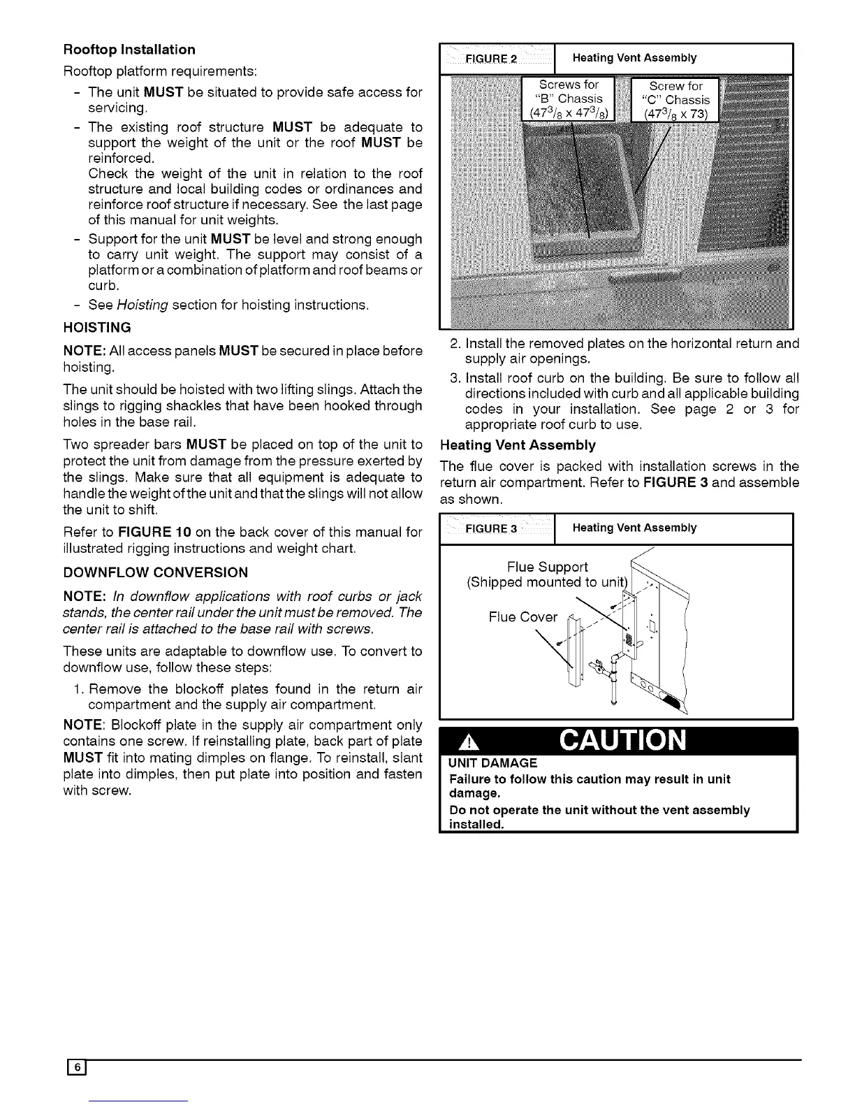
I FIGURE2 1 Heating Vent Assembly
Screws for Screw for
"B" Chassis "C" Chassis
(473/8 x 473/8) (473/8 x 73)
I
2. Install the removed plates on the horizontal return and
supply air openings.
3, Install roof curb on the building. Be sure to follow all
directions included with curb and all applicable building
codes in your installation. See page 2 or 3 for
appropriate roof curb to use.
Heating Vent Assembly
The flue cover is packed with installation screws in the
return air compartment, Refer to FIGURE 3 and assemble
as shown,
FIGURE 3 1 Heating Vent Assembly
Flue Support
(Shipped mounted to unit
Flue Cover
UNIT DAMAGE
Failure to follow this caution may result in unit
damage.
Do not operate the unit without the vent assembly
installed.
161
 Loading...