CONTINUOUSFANOPERATION
Continuousfanspeedoperatesatthe lowstagecooling
speedforallmodels.
COOLING
1.TurnelectricpowerOFF
2.SetthermostatHeat-Coolselectto COOL.
3.Adjustthermostatsettingto belowroomtemperature.
4.TurnpowerON,for approximatelyoneminute,then
OFF.Duringpowerapplicationcheckthefollowing:
a.Contactor- ContactsClosing
b.Compressor- ON
c.Condenserfanmotor- ON
d.CirculatingAirBlower- ON0 seconddelay
5.TurnpowerOFEcheckthefollowing:
a. Contactorcontactsopening.
b. Compressor- OFF
c. Condenserfanmotor- OFF
d. Circulatingblower- OFFafter90seconddelayon
allmodels.
9. START-UP PROCEDURES
FIRE OR EXPLOSION HAZARD
Failure to follow this warning could result in personal
injury, death and/or property damage.
Do NOT attempt to light the burner with a match or
flame of any kind.
CHECK BEFORE STARTING
1. Check that the blower motor speed terminal block is
running the correct heating and cooling speeds.
2. Check to see that clean, properly sized air filters are
installed.
3. Replace all service access panels.
FIRE OR EXPLOSION HAZARD.
Failure to follow this warning could result in
personal injury and/or death.
Turn OFF gas at shut off before connecting U-tube
manometer.
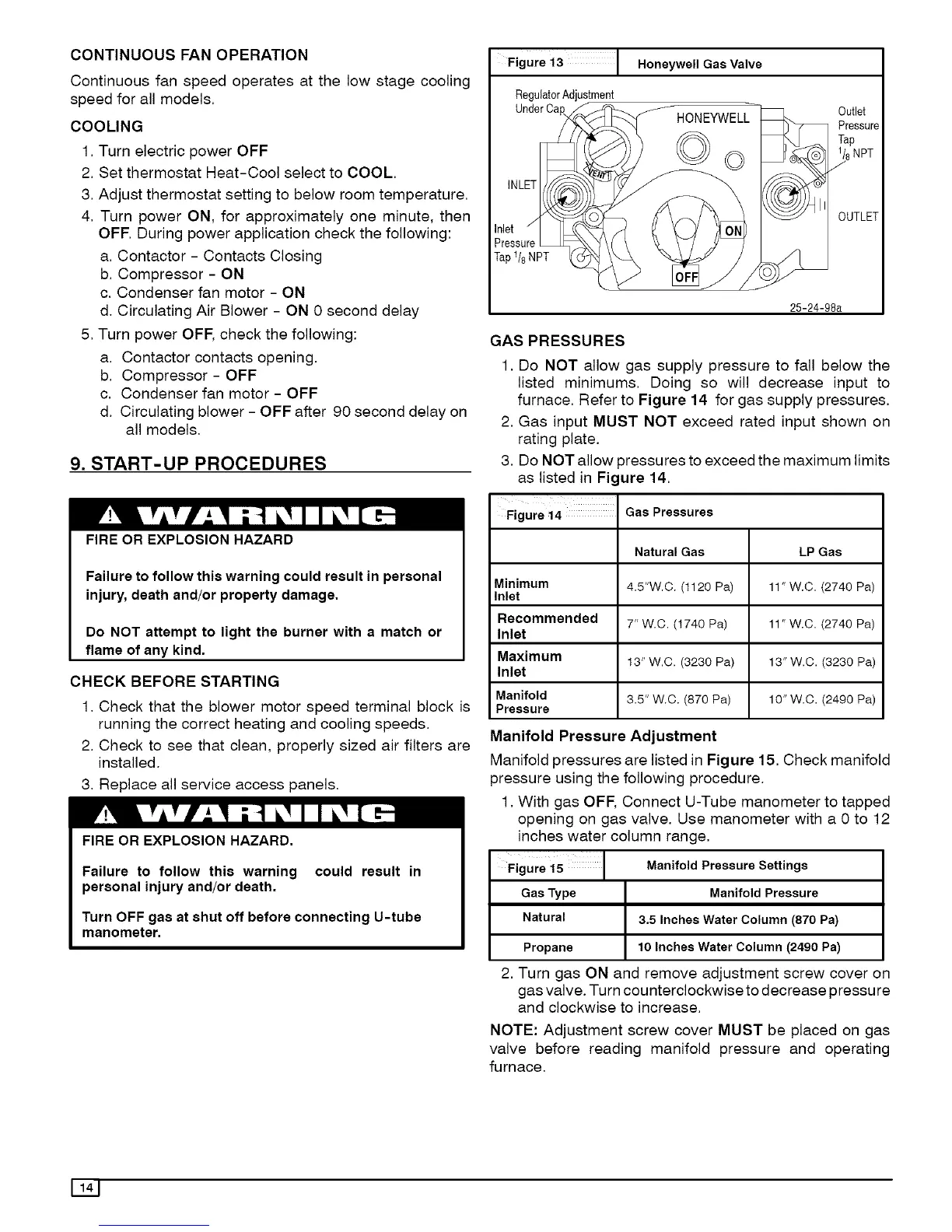
Figure i3 I Honeywell Gas Valve
RegulatorAdjustment
UnderCa
Inlet
Pressure
Tap1/8NPT
HONEYWELL
©
Outlet
Pressure
Tap
1/8NPT
/
OUTLET
25-24-98a
GAS PRESSURES
1. Do NOT allow gas supply pressure to fall below the
listed minimums. Doing so will decrease input to
furnace. Refer to Figure 14 for gas supply pressures.
2. Gas input MUST NOT exceed rated input shown on
rating plate.
3. Do NOT allow pressures to exceed the maximum limits
as listed in Figure 14.
Figure 14
Gas Pressures
Natural Gas LP Gas
Minimum 4.5"W.C. (1120 Pa) 11" W.C. (2740 Pa)
Inlet
Recommended 7" W.C. (1740 Pa) 11" W.C. (2740 Pa)
Inlet
Maximum 13" W.C. (3230 Pa) 13" W.C. (3230 Pa)
Inlet
Manifold 3.5" W.C. (870 Pa) 10" W.C. (2490 Pa)
Pressure
Manifold Pressure Adjustment
Manifold pressures are listed in Figure 15. Check manifold
pressure using the following procedure.
1. With gas OFE Connect U-Tube manometer to tapped
opening on gas valve. Use manometer with a 0 to 12
inches water column range.
Figure 15 Manifold Pressure Settings
Gas Type Manifold Pressure
Natural 3.5 Inches Water Column (870 Pa)
Propane 10 Inches Water Column (2490 Pa)
2. Turn gas ON and remove adjustment screw cover on
gas valve. Turn counterclockwise to decrease pressure
and clockwise to increase.
NOTE: Adjustment screw cover MUST be placed on gas
valve before reading manifold pressure and operating
furnace.
1141
 Loading...