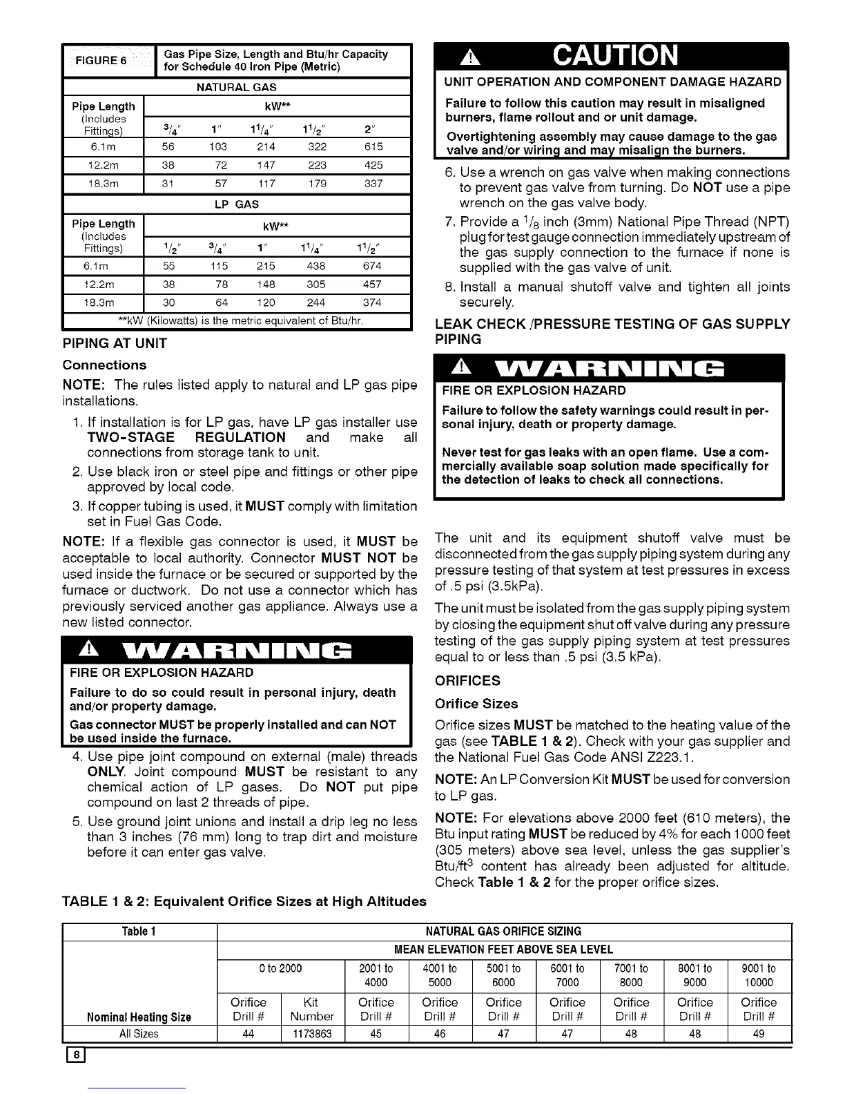
FIGURE 6 Gas Pipe Size, Length and Btu/hr Capacity
for Schedule 40 Iron Pipe (Metric)
NATURAL GAS
Pipe Length kW**
(includes
Fittings) 3/4" 1" 11/4 " 11/2" 2"
6.1m 56 103 214 322 615
12.2m 38 72 147 223 425
18.3m 31 57 117 179 337
LP GAS
Pipe Length kW**
(includes
Fittings) 1/2" 3/4" 1" 11/4 " 11/2 "
6.1m 55 115 215 438 674
12.2m 38 78 148 305 457
18.3m 30 64 120 244 374
**kW (Ki!owatts) is the metric equivalent of Btu/hr.
PIPING AT UNIT
Connections
NOTE: The rules listed apply to natural and LP gas pipe
installations.
1. If installation is for LP gas, have LP gas installer use
TWO-STAGE REGULATION and make all
connections from storage tank to unit.
2. Use black iron or steel pipe and fittings or other pipe
approved by local code.
3. If copper tubing is used, it MUST comply with limitation
set in Fuel Gas Code.
NOTE: If a flexible gas connector is used, it MUST be
acceptable to local authority. Connector MUST NOT be
used inside the furnace or be secured or supported by the
furnace or ductwork. Do not use a connector which has
previously serviced another gas appliance. Always use a
new listed connector.
FIRE OR EXPLOSION HAZARD
Failure to do so could result in personal injury, death
and/or property damage.
Gas connector MUSTbe properly installedand can NOT
be used inside the furnace.
4. Use pipe joint compound on external (male) threads
ONLY. Joint compound MUST be resistant to any
chemical action of LP gases. Do NOT put pipe
compound on last 2 threads of pipe.
5. Use ground joint unions and install a drip leg no less
than 3 inches (76 mm) long to trap dirt and moisture
before it can enter gas valve.
TABLE 1 & 2: Equivalent Orifice Sizes at High Altitudes
UNIT OPERATION AND COMPONENT DAMAGE HAZARD
Failure to follow this caution may result in misaligned
burners, flame rollout and or unit damage.
Overtightening assembly may cause damage to the gas
valve and/or wirin_land may misali_lnthe burners.
6. Use a wrench on gas valve when making connections
to prevent gas valve from turning. Do NOT use a pipe
wrench on the gas valve body.
7. Provide a t/8 inch (3mm) National Pipe Thread (NPT)
plug for test gauge connection immediately upstream of
the gas supply connection to the furnace if none is
supplied with the gas valve of unit.
8. Install a manual shutoff valve and tighten all joints
securely.
LEAK CHECK/PRESSURE TESTING OF GAS SUPPLY
PIPING
FIRE OR EXPLOSION HAZARD
Failure to follow the safety warnings could result in per-
sonal injury, death or property damage.
Never test for gas leaks with an open flame. Use a com-
mercially available soap solution made specifically for
the detection of leaks to check all connections.
The unit and its equipment shutoff valve must be
disconnected from the gas supply piping system during any
pressure testing of that system at test pressures in excess
of .5 psi (3.5kPa).
The unit must be isolated from the gas supply piping system
by closing the equipment shut off valve during any pressure
testing of the gas supply piping system at test pressures
equal to or less than .5 psi (3.5 kPa).
ORIFICES
Orifice Sizes
Orifice sizes MUST be matched to the heating value of the
gas (see TABLE 1 & 2). Check with your gas supplier and
the National Fuel Gas Code ANSI Z223.1.
NOTE: An LP Conversion Kit MUST be used for conversion
to LP gas.
NOTE: For elevations above 2000 feet (610 meters), the
Btu input rating MUST be reduced by 4% for each 1000 feet
(305 meters) above sea level, unless the gas supplier's
Btu!ft3 content has already been adjusted for altitude.
Check Table 1 & 2 for the proper orifice sizes.
Table1 NATURALGASORIFICESIZING
MEANELEVATIONFEETABOVESEALEVEL
0 to 2000 2001to 4001to 5001to 6001to 7001to 8001to 9001to
4000 5000 6000 7000 8000 9000 10000
Orifice Kit Orifice Orifice Orifice Orifice Orifice Orifice Orifice
NominalHeatingSize Drill # Number Drill # Drill # Drill # Drill # Drill # Drill # Drill #
All Sizes 44 1173863 45 46 47 47 48 48 49
181
 Loading...