NOTE: The orifice sizes in the chart above derate the input rate at 4% per 1000 feet above sea level for altitudes exceeding 2000 feet
above sea level. If converting from LP gas to Natural Gas at altitudes exceeding 2000 feet above sea level, use part number
330732-401, plus the required orifice size # shown in Table 1. Natural Gas data is based on 0.60 specific gravity, a heating value of 1030
Btu/ft3., and 3.5" W.C. manifold pressure. For fuels with different specific gravity, consult the National Fuel Gas Code NFPA
54-2005/ANSI Z223.1-2005 or National Standard of Canada, Natural Gas and Propane Installation Code CSA B149.1-05.
Table 2 LP GAS ORIFICE SIZING
MEAN ELEVATION FEET ABOVE SEA LEVEL
0 to 2000 2001 to 4000 4001 to 7000 7001 to 9000 9001 to 10,000
Nominal Heating Orifice Kit Orifice Kit Orifice Kit Orifice Kit Orifice Kit
Size Drill # Number Drill # Number Drill # Number Drill # Number Drill # Number
All Sizes 55 1173857 55 1173857 56 1173859 56 1173859 57 1173861
NOTE: The orifice sizes in the chart above derate the input rate at 4% per 1000 feet above sea level for altitudes exceeding 2000 feet
above sea level. LP Gas data is based on 1.52 specific gravity, a heating value of 2500 Btu/ft3., and 10.0" W.C. manifold pressure. For
fuels with different specific gravity, consult the National Fuel Gas Code NFPA 54-2005/ANSI Z223.1-2005 or National Standard of
Canada, Natural Gas and Propane Installation Code CSA B149.1-05.
Changing Orifices
ELECTRICAL SHOCK, FIRE AND/OR EXPLOSION
HAZARD
Failure to follow this warning could result in personal
injury, death and/or property damage.
Shut off electric power at unit disconnect or service
panel and shut off gas at manual shut off valve before
beginning the following procedure.
Changing orifices requires a qualified service
technician.
1. Shut OFF gas at manual shut off valve.
2. Shut OFF electric power at unit disconnect or service
panel. If unit is still running, allow 3 minutes after gas
shut off before turning off power.
3. Disconnect the wires from the gas valve, sparker, and
flame sensor.
4. Remove the four screws holding the manifold to the
manifold brackets.
5. Carefully remove the manifold with the gas valve
attached.
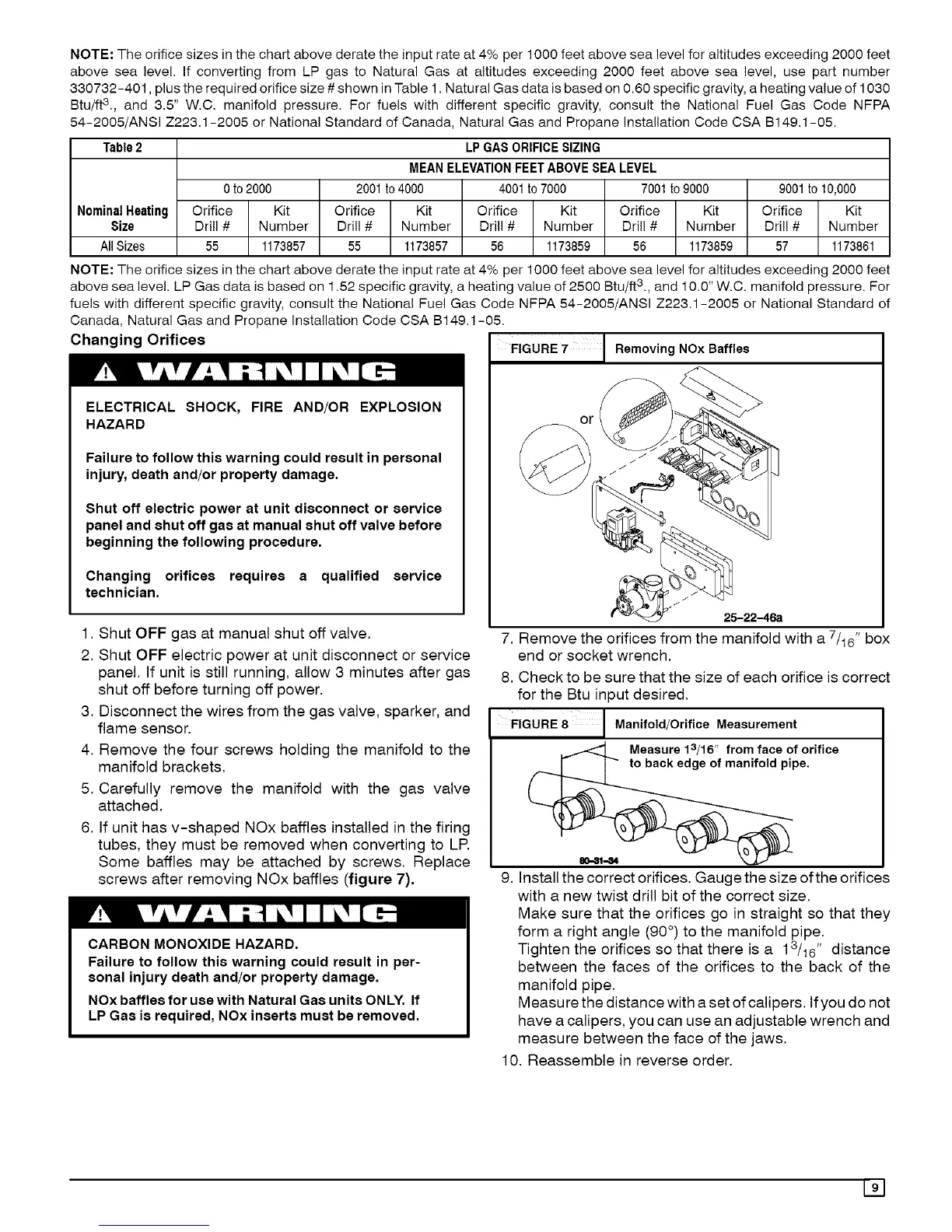
6. If unit has v-shaped NOx baffles installed in the firing
tubes, they must be removed when converting to LR
Some baffles may be attached by screws. Replace
screws after removing NOx baffles (figure 7).
CARBON MONOXIDE HAZARD.
Failure to follow this warning could result in per-
sonal injury death and/or property damage.
NOx baffles for use with Natural Gas units ONLY. If
LP Gas is required, NOx inserts must be removed.
FIGURE 7 Removing NOx Baffles
25-22-46a
7. Remove the orifices from the manifold with a 7/t6" box
end or socket wrench.
8. Check to be sure that the size of each orifice is correct
for the Btu input desired.
FIGURE 8 Manifold/Orifice Measurement
Measure 13/16 " from face of orifice
_ _ifold pipe.
9. Install the correct orifices. Gauge the size ofthe orifices
with a new twist drill bit of the correct size.
Make sure that the orifices go in straight so that they
form a right angle (90 °) to the manifold pipe.
Tighten the orifices so that there is a ] 3/t6" distance
between the faces of the orifices to the back of the
manifold pipe.
Measure the distance with a set of calipers. Ifyou do not
have a calipers, you can use an adjustable wrench and
measure between the face of the jaws.
10. Reassemble in reverse order.
191
 Loading...