I Combination Units
Inspection And Cleaning Of Burner
Assembly/Heat Exchangers/Flue Gas
Passages
Installation Instructions
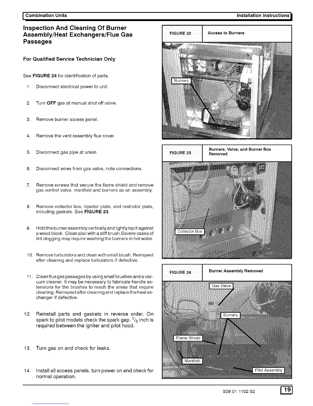
Access to Burners
For Qualified Service Technician Only
See FIGURE 24 for identification of parts.
1. Disconnect electrical power to unit.
2. Turn OFF gas at manual shut off valve.
3. Remove burner access panel.
4. Remove the vent assembly flue cover.
5. Disconnect gas pipe at union.
6. Disconnect wires from gas valve, note connections.
Burners, Valve, and Burner Box
Removed
7. Remove screws that secure the flame shield and remove
gas control valve, manifold and burners as an assembly.
8. Remove collector box, injector plate, and restrictor plate,
including gaskets. See FIGURE 23.
9. Hold the burner assembly vertically and lightly tap it against
a wood block. Clean also with a stiff brush.Severe cases of
lint clogging may require washing the burners in hot water.
10.
11.
12.
Remove turbulators and clean with small brush. Reinspect
after cleaning and replace turbulators if defective.
Clean flue gas passages by using small brushes and avac-
uum cleaner. It may be necessary to fabricate handle ex-
tensions for the brushes to reach the areas that require
cleaning. Reinspect after cleaning and replace the heat ex-
changer if defective.
Reinstall parts and gaskets in reverse order. On
spark to pilot models check the spark gap. 1/8 inch is
required between the igniter and pilot hood.
13. Turn gas on and check for leaks.
14.
Install all access panels, turn power on and check for
normal operation.
EiGURE 24 Burner Assembly Removed
Gas Valve
50901 110202 [_