6 Innovative Circuit Technology Ltd.
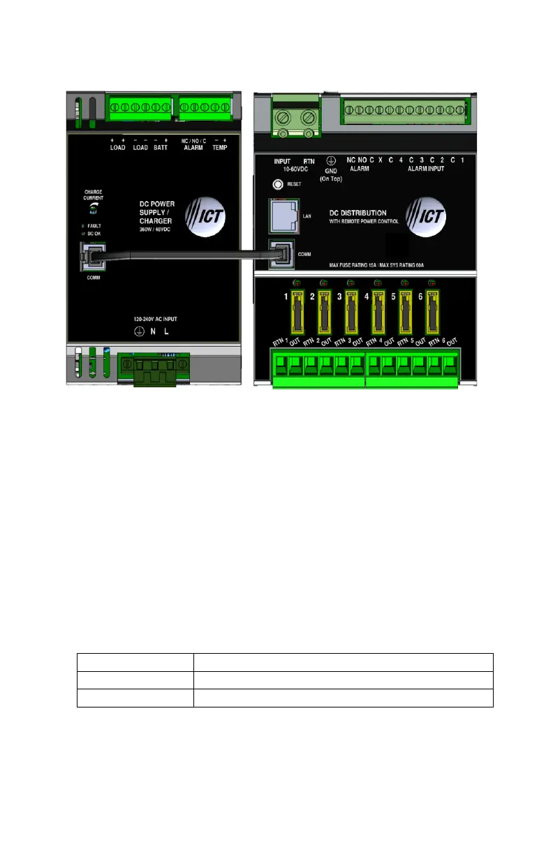
supply. Install the PDU and power supply units side by side, then connect the two
RJ-11 COMM ports together using the data cable, as shown in Figure 3.
Figure 3. Connection between ICT DIN Power supply and ICT-DIN-PDU6
6. The Alarm Form “C” contacts on the back of the PDU can be connected to an
external alarm circuit to monitor alarms generated by the PDU. Depending on
the alarm circuit (refer to table 2), connect it between normally open (NO) and
common (C), between normally closed (NC) and common (C), or both. The built-
in web server controls this alarm. The alarm connector can be unplugged from
the PDU for easy installation.
7. For monitoring external Dry Contact sensors, connect each sensor between an
Alarm Input (1 - 4) and common (C) on the alarm input connector. The alarm
input connector can be unplugged from the PDU for easy installation. Refer to
table 3 for the alarm input connector pin-out.
Table 1: Fuse Status LED
 Loading...