Comfosplit IKARO HW – User and Installer manual EN
© Ideal Clima - Page 63 of 68
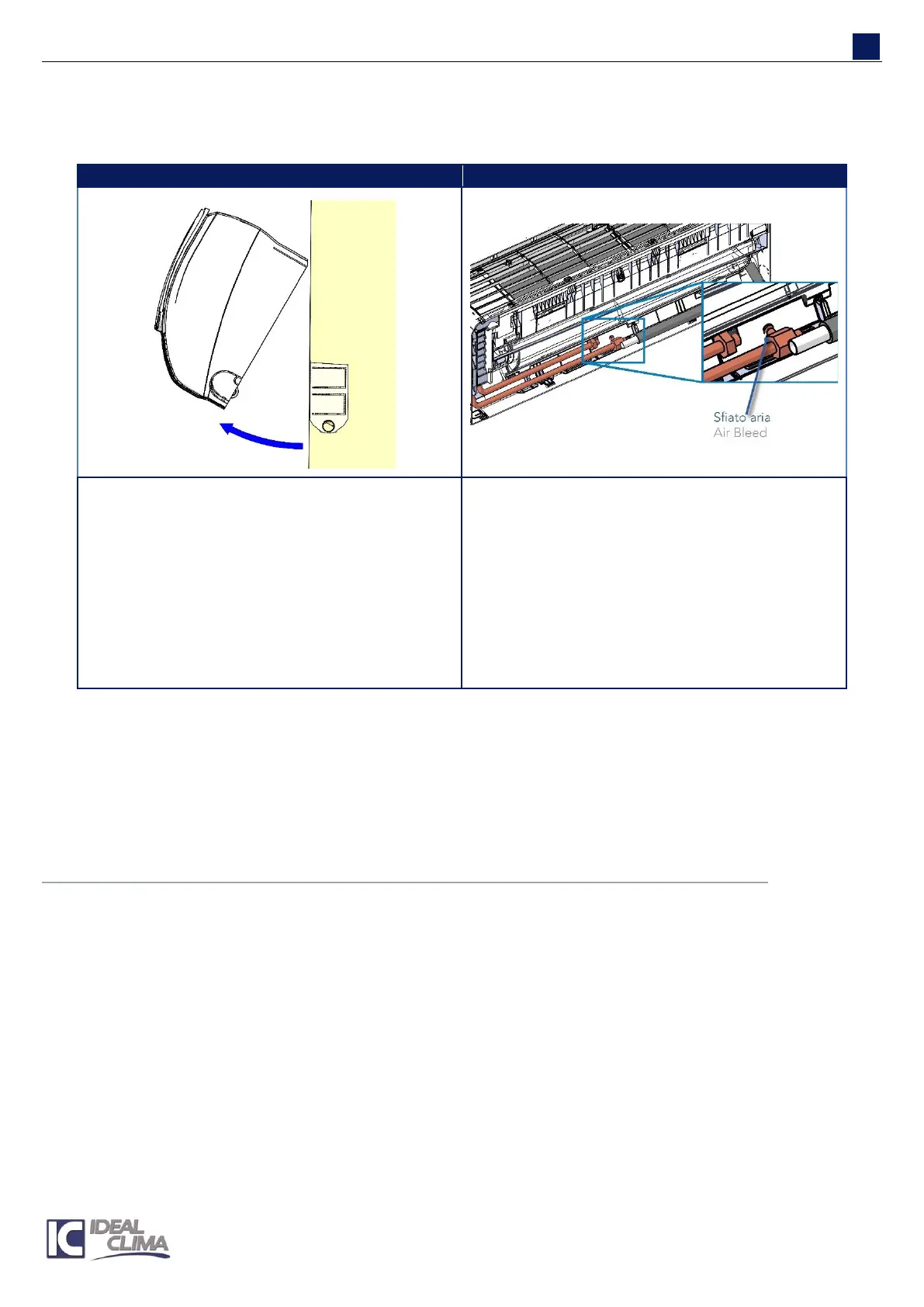
WATER FILLING AND AIR VENTING
Open any shut-off valves and fill with water.
With the help of a wedge, keep the unit tilted as
in the picture, until the electrical and hydraulic
connections have been completed.
The air vent is located as indicated in the figure.
The drain valve is placed on the water return
duct and has a small handwheel, similar to that
of radiators.
Open the vent to let the air contained in the
heat exchanger to escape. Close the vent when
you see only water coming out.
To the handwheel a small duct can be
connected (not supplied), to facilitate the
venting operations.
PRESSURE TEST
Close the hydraulic circuit effectively disconnecting the appliance if the system should be tested at higher
pressure than the appliance working pressure (16 bar). Testing the unit at a pressure of 1.5 times higher than the
heating system design operating pressure, in any case not higher than16 bar.
PIPE INSULATION
Insulate all pipes that are located outside the predisposition box. Insulating adhesive tape can be used (cod.
VPNA02)
19.7 ELECTRICAL CONNECTION
POWER SUPPLY 230V
IKARO is equipped with a power cord for connection to the electricity mains. It is not necessary any
intervention into the electrical box if you do not mount 2- or 2-way valve with actuators and you use IR remote
control to manage the unit.