82
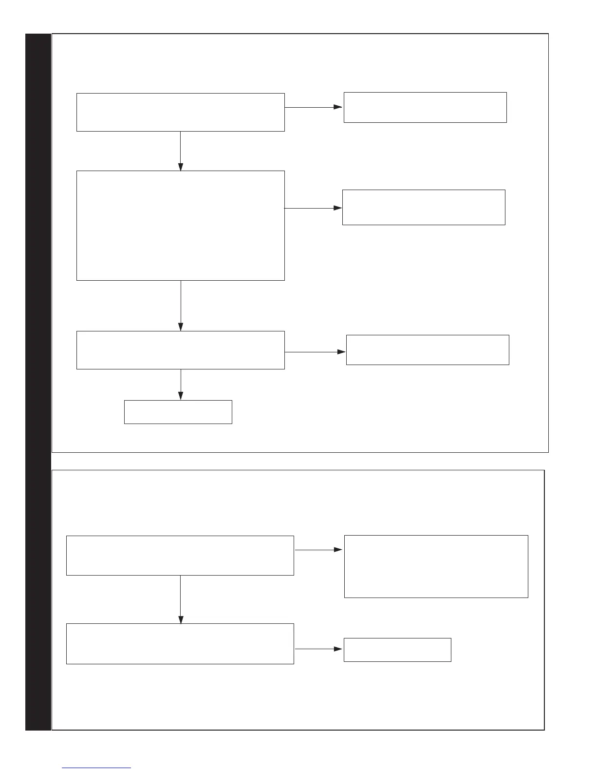
OUTSIDE SENSOR FAULT - CONTACT INSTALLER
Disconnect the wires to the outside sensor.
Check the resistance using a suitable multimeter
connected across the Outside Sensor’s terminal pins.
At 0
o
C expect 31,000 - 35,000 Ohms
At 15
o
C expect 15,000 - 16,500 Ohms
At 30
o
C expect 7,700 - 8,500 Ohms
Is the Outside Sensor value correct?
YES
YES
Is the wiring securely connected between the
incoming terminal block boiler connection of the
Outside Sensor and the PCB?
Replace PCB
Fit a new Outside Sensor
NO
Securely connect the wiring at the
Terminal Block and the PCB
Is the wiring securely connected at both the boiler and
Outside Sensor?
YES
NO
Securely connect the wiring at both the
boiler and Outside Sensor
NO
83
BOILER CHIP CARD FAULT - CONTACT INSTALLER
Is the correct BCC for the boiler securely inserted into the
slot at the front left of the PCB?
(identied by the label on the BCC)
YES
NO
Securely attach the correct BCC for the boiler
onto the PCB and after switching power on and
‘c0’ being shown, reset the boiler.
Note. Ensure the correct orientation of BCC by
placing “TOP” side up.
Replace the BCC with a new BCC (that is correct for the
boiler). After switching power on and ‘c0’ being shown,
reset the boiler. Is ‘c2’ still shown?
Replace PCB
YES
RESET PROCEDURE - To reset boiler, turn mode knob to reset position and immediately turn knob back to required setting.