85
TILT-A-WAY HYDRAULIC VERTICAL PIVOT GATE
GENERAL ARRANGEMENT AND MAINTENANCE
MAINTENANCE MUST BE DONE EVERY 5000 OPERATIONS OR YEARLY
HYJG 1
DWG # HYJG-244
TILT-A-WAY
GENERAL MAINTENANCE
HYJg-244
Check all safety devices for proper function monthly.
Check interior of pedestal for any accumulation of trash caused by blowing wind and
remove. (Monthly).
The following maintenance steps should be preformed every 5000 operations or yearly.
1. Check hydraulic fluid level with site gauge on oil reservoir. Level to be
approximately 2 ½” below the top of reservoir. If oil is required, add Citgo-CP
hydraulic fluid (this hydraulic fluid is blue in color). Check oil level with cylinder
retracted.
2. Clean and lubricate spring tension screws with “general purpose grease” to
prevent rusting.
3. Lubricate with “general purpose grease such as a bearing grease” all points
equipped with zerk fitting.
A. Barrier carriage pivot bearing. Two bearings one each side.
B. Cylinder anchor pivot.
C. Cylinder rod end pivot bearing.
4. Check gate balance. Open gate to mid travel, and stop. Turn power off, and open
manual valves on front of hydraulic pump unit. Gate should remain at mid travel
position. If gate moves see page 68 for balance adjustment. Close manual valves,
and turn power on. Return gate to closed position.
5. Inspect balance cables for broken strands. Replace cable if there are five broken
strands per lay or ten broken strands over all. See page 71 for cable replacement
instructions.
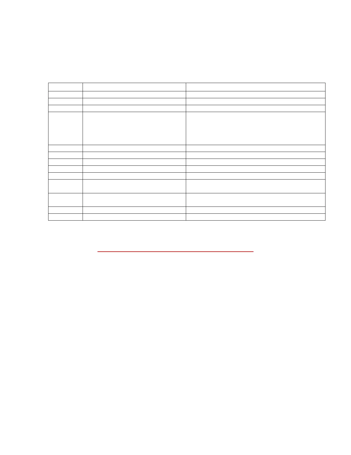
REF NO.
DESCRIPTION
For covering. See Drawing
Hydraulic Pump & Reservoir
Electrical Control Enclosure
24 VDC 120 VAC
208 / 240 VAC Single Phase
208 /240 VAC Three Phase
480 VAC Three Phase
See Drawing HYJG-204 Page 9
See Drawing HYJG-207 Page 13
See Drawing HYJG-210 Page 17
See Drawing HYJG-213 Page 21
Balance System Cable Guide Assembly.
Balance System Tension Cable
Balance system Tension Spring
Balance System Spring Tension
Adjusting Limit
ety Switch”. See Drawing HYJG
Page 87
Hydraulic Actuating Cylinder
Cylinder Control Actuating System
 Loading...