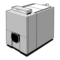
INSTALLATION
vogue system boiler - Installation and Servicing
INSTALLATION
INSTALLATION
40
MENU OPERATION
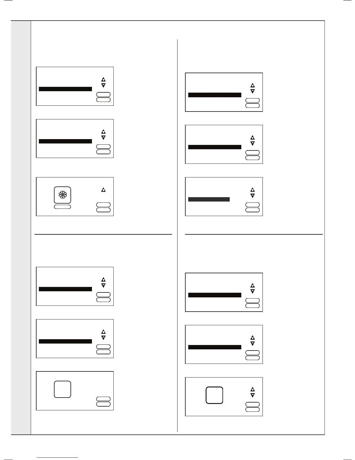
SYSTEM FROST PROTECTION
This feature can only be accessed if an outside sensor
has been connected. The pump will run continuously if the
outside temperature is less than 5
o
C.
Press “-” until the following screen is displayed.
Press ENTER and a screen similar to the following will be
displayed.
Pump may run during night
Press “+” to activate or “-“ to de-activate.
Press EXIT twice to return to normal operation.
RESET SERVICE TIME
If the boiler has not been serviced within the last 12 months
then a message will be displayed indicating this. To reset this
timing proceed as follows.
Press “-” until the following screen is displayed.
Press ENTER and the following screen will be displayed.
Press ENTER to reset.
Press EXIT to return to normal operation.
PLOT GRAPHS
To plot graphs of Water Pressure, Switched Live, Flow/Return
Temperature, Flame Status, Outside Temperature or Cylinder
Switched Live press ENTER and the following screen will be
displayed.
Press “-“ until the following screen is displayed.
Press ENTER and the following screen will be displayed.
Press “+” & “-“ to highlight the desired input and then ENTER to
select. Press EXIT 3 times to return to normal operation.
BUS ADDRESS
This feature is only required if the boiler is connected to an
Ideal Cascade Manager (available 2014). Each boiler in the
cascade should be congured to a different bus address. To
change the bus address press ENTER.
Press “-“ until the following screen is displayed.
Press ENTER and a screen similar to following will be displayed.
Multiple Boiler Installations
Press “+” or “-“ to change the address.
Press ENTER and then EXIT to return to normal operation.
 Loading...